
Installation Manual

7.
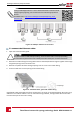
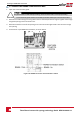
ConnectthecableRJ45connectortotheRJ45portoftheEthernetswitchorrouter.
Youcanconnectmorethanoneinvertertothesameswitch/routerortodifferentswitches/routers,
asneeded.EachinvertersendsitsmonitoreddataindependentlytotheSolarEdgemonitoring
platform.
NOTE
There are no LED indicators on the Ethernet connector, if the inverter is not communicating with
the monitoring platform through a LAN refer toTroubleshooting Communication on page 74.
8.
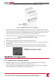
TheinverterisconfiguredbydefaulttoLAN.Ifreconfigurationisrequired:
a. VerifytheON/OFFswitchisOFF.
b. VerifytheACison.
c.
ClosethecoverandturnONtheConnectionUnit.
WARNING!
ELECTRICAL SHOCK HAZARD. Do not touch uninsulated wires when the Connection Unit
over is removed.
RISQUE D’ÉLECTROCUTION, ne touchez pas les fils non isolés lorsque le couvercle de
l'onduleur est retiré.
d. UsetheSolarEdgeSetApptoaccesstheCommissioningmainmenuscreenasdescribedin
Communicationonpage42.
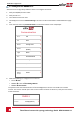
e.
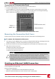
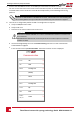
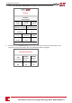
FromthemainmenutapCommunication.TheCommunicationscreenisdisplayed:
Communication
Server LAN
›
LAN DHCP
›
RS485-1 SolarEdge Slave
›
RS485-2
Multi -Device
(Modbus)
›
ZigBee
Home Automation
Master
›
Wi-Fi SEDG-7E129A09-33
›
RS232 SolarEdge GSM
Cellular N/A
›
GPIO RRCR
›
Modbus
TCPport
Disable
›
Three Phase Inverter with synergy technology Guide MAN-01-00401-1.1
63
Creating an Ethernet (LAN) Connection