
Installation Manual
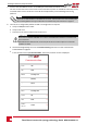

RJ45 Pin #
Wire Color
1
10Base-T Signal
100Base-TX Signal
T568B T568A
1 White/Orange White/Green Transmit+
2 Orange Green Transmit-
3 White/Green White/Orange Receive+
4 Blue Blue Reserved
5 White/Blue White/Blue Reserved
6 Green Orange Received-
7 White/Brown White/Brown Reserved
8 Brown Brown Reserved
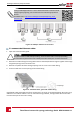
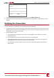
Figure 34: Standard cable wiring
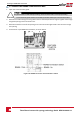
5. Useapre-crimpedcabletoconnectviatheglandtotheRJ45portontheinverter'scommunication
boardor,ifusingaspoolofcable,connectasfollows:
a. Insertthecablethroughthegland.
b. Removethecable’sexternalinsulationusingacrimpingtoolorcablecutterandexposeeight
wires.
c. InserttheeightwiresintoanRJ45connector,asdescribedFigure34.
d. Useacrimpingtooltocrimptheconnector.
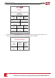
e. ConnecttheEthernetconnectortotheRJ45portonthecommunicationboardasshownin
Figure34.
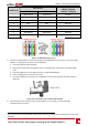
Figure 35: Connection Unit Communication board
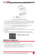
6. Fortheswitch/routerside,useapre-crimpedcableoruseacrimpertoprepareanRJ45
communicationconnector.
1
The connection does not support RX/TX polarity change. Supporting crossover Ethernet cables depends on the switch
capabilities.
Chapter 6: Setting Up Communication
Three Phase Inverter with synergy technology Guide MAN-01-00401-1.1
62