
Installation Manual

NOTE
If using a cable longer than 10 m / 33 ft in areas where there is a risk of induced
voltage surges by lightning, it is recommend to use external surge protection
devices.
For details refer to: http://www.solaredge.us/files/pdfs/lightning_surge_
protection.pdf.
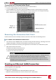
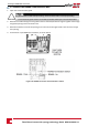
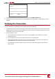
Figure 32: Example of Ethernet connection
To connect the Ethernet cable:
1. Openthecommunicationgland.
CAUTION!
The gland includes a rubber waterproof fitting, which should be used to ensure proper sealing.
Le cote interne du gland contient une rondelle qui doit être utilisée pour une bonne étancheïté.
2. RemovetherubberfittingfromtheglandandinserttheCAT5/6cablethroughtheglandandthrough
theglandopeningintheConnectionUnit.
3. Removetheplasticsealfromthelargeopeningthathasacutintherubberfitting.
4.
Pushthecableintothecutopeningoftherubberfitting.
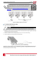
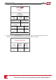
Figure 33: Communication gland and rubber fitting
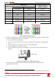
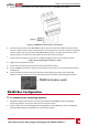
CAT5/5ESTPcableshaveeightwires(fourtwistedpairs),asshowninthediagrambelow.Wirecolorsmay
differfromonecabletoanother.Youcanuseeitherwiringstandard,aslongasbothsidesofthecable
havethesamepin-outandcolor-coding.
Three Phase Inverter with synergy technology Guide MAN-01-00401-1.1
61
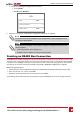
Creating an Ethernet (LAN) Connection