
Installation Manual
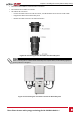
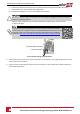

b. Insertthescrewdriverandfirmlytiltittopressthereleasemechanismandopentheclamp.
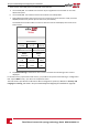
c. Insertthewireintothetopopening(seeFigure26).
d. Removethescrewdriver–thewireisautomaticallyclamped.
CAUTION!
Ensure that the Plus (+) wire is connected to the + terminal and that the Minus (-) wire is connected to
the Minus (-) terminal connector.
VeillezàcequelecâblePlus(+)soitconnectéauterminal+etquelecâble-soitconnectéau
connecteurterminal.
NOTE
For systems with four PV strings per unit or more, fuses may need to be installed in
both the positive and negative conductors as required by NEC Article 690.9. For more
information, refer to the Technical Note “String Fusing Requirements in SolarEdge
Systems” at http://www.solaredge.com/files/pdfs/string_fusing_requirements.pdf.
Figure 26: DC Spring-clamp terminals
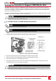
5. ClosetheConnectionUnitcover:Attachtheswitchcoverandsecureitbytighteningthefourscrews
withatorqueof1.20.9ft.*lb.
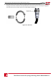
6. Ensureproperconduitsealing;inspecttheentireconduitrunandusestandardconduitsealantsto
avoidwaterpenetration.
Three Phase Inverter with synergy technology Guide MAN-01-00401-1.1
35
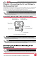
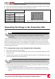
Connecting the Strings to the Connection Unit