
Installation Manual
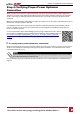
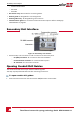

l LiftthePrimaryUnitfromitssides.
l Alignthetwoindentationsintheenclosurewiththetwotriangularmountingtabsofthebracket,
andlowertheunituntilitrestsonthebracketevenly(seeFigure18).
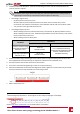
l Insertthesuppliedscrewthroughtherightsideoftheheatsinkandintothebracket
Figure 18: Hanging units
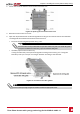
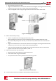
8. MounttheSecondaryUnit(s):
l ThereisnospecificorderforhangingtheSecondaryUnits.
Wheninstallinga2unitinverter,mounttheSecondaryUnittotheleftofthePrimaryUnit.
l LifttheSecondaryUnit(s)fromthesides,orholditatthetopandbottomoftheunittoliftinto
place.
l Alignthetwoindentationsintheenclosurewiththetwotriangularmountingtabsofthebracket,
andlowertheunituntilitrestsonthebracketevenly(seeFigure18).
l Insertoneofthesuppliedscrewsthroughtheoutersideoftheheatsinkandintothebracket.
Tightenthescrewswithatorqueof4.0N*m/2.9lb.*ft.
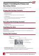
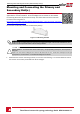
9. SecuretheConnectionUnittothewall:
l Markthelocationofthebracketscrewanddrillthehole
l Fastenthebracketusingastandardbolt
l Verifythatthebracketisfirmlyattachedtothemountingsurface
Figure 19: Connection Unit bracket
10. ConnecttheConnectionUnitcablestotheSecondaryUnit(s)connectors.
Three Phase Inverter with synergy technology Guide MAN-01-00401-1.1
29
Mounting and Connecting the Primary and Secondary Unit(s)