
Installation Manual

2.
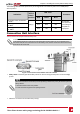
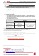
Toallowproperheatdissipation,maintainthefollowingminimumclearanceareasbetweenthe
inverterandotherobjects:
NOTE
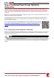
The Primary unit is longer than the Secondary Unit, therefore make sure the mounting location is
high enough to fit the Primary Unit and leaves sufficient space for cable entry.
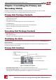
l Ifinstallingasingleinverter:
o
8"(20cm)fromthetopoftheunit.
o
Atleast4"(10cm)fromthebottomoftheConnectionUnit;ifconduitentrytothe
ConnectionUnitwillbefromthebottom,leavesufficientclearancefortheconduitsaswell.
o
1.2"(3cm)fromtherightandleftoftheunit.
l Ifinstallingmultipleinverters:
o
Wheninstallinginvertersoneaboveoftheother,leaveatleast12"(30cm)betweeninverter.
WheninstallingthePrimaryUnit,leave20cm(8")betweenthetopofanPrimaryUnitandthe
bottomoftheConnectionUnit.
o
Wheninstallinginverterssidebyside:
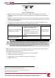
Location
Clearance
Indoor Installation Outdoor Installation
Locations where the annual
average high temperature
1
is
below 25˚C / 77˚F
20 cm / 8"
between inverters
5 cm / 2" between inverters (if
inverters are also installed one above
the other, maintain the indoor
installation clearance)
Locations where the annual
average high temperature
1
is
above 25˚C / 77˚F
40 cm / 16"
between inverters
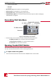
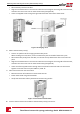
3.
Positionthemountingbracketsagainstthewallandmarktherequireddrillingholeslocationswith
thesuppliedlevel.Thelevelmarkingscorrespondtoadistanceof3cmbetweenunits
4. Drilltwoholesforeachbracketandmountthebrackets.
5. Putinthescrewswithouttighteninginordertocorrectpositioning.
6.
Placethelevelbeneaththebracketsandalignthebrackets,tightenthescrewsallthewayandverify
thatthebracketsarefirmlyattachedtothemountingsurface.
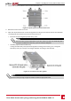
7. MountthePrimaryUnit:
1
Annual average high temperature – the average of the 12 monthly average highs, for example:
Refer to http://www.weatherbase.com/ to find the value in your location.
Chapter 3: Installing the Primary and Secondary Unit(s)
Three Phase Inverter with synergy technology Guide MAN-01-00401-1.1
28