
Installation Manual

2.
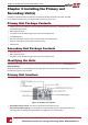
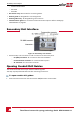
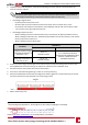
LoosenthescrewsonthefrontcoveroftheConnectionUnit.
Figure 15: Opening the Connection Unit cover
3. RemovetheConnectionUnitcover.
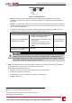
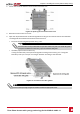
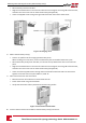
4. OpentherequiredACandDCconduitdrillguidesaccordingtotheconduitsusedintheinstallation.
Thedrillguidesarelocatedatthebottomoftheenclosure.
l
KnockouttheDCdrillguide(conduitentry)1.25".
NOTE
The Connection Unit is provided with one open DC conduit entry with one closed drill guide. If
you require an additional conduit entry, open the closed DC drill guide.
l Ifneeded,opentheACconduitentry.
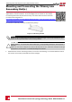
IfusingoneSecondaryUnitopenthedrillguideaccordingtothemarking1.5".Ifusingtwo
SecondaryUnitsyoucanopenittoalargerdiameteraccordingtothecablesize.
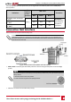
Figure 16: Connection Unit drill guides
NOTE
Unused conduit openings and glands should be sealed with appropriate seals.
Chapter 3: Installing the Primary and Secondary Unit(s)
Three Phase Inverter with synergy technology Guide MAN-01-00402-1.1
26