
Installation Manual
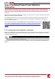
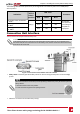
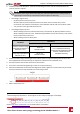

l ON/OFF/P Switch:
Figure 11: ON/OFF/P switch
o
ON (1)-TurningthisswitchON(afteroptimizerpairing)startstheoperationofthepower
optimizers,enablespowerproductionandallowstheinvertertobeginexportingpowertothe
utilitygrid
o
OFF (0)-TurningthisswitchOFFreducesthepoweroptimizervoltagetoalowsafetyvoltageand
inhibitsexportationofpower.WhenthisswitchisOFF,thePrimaryandSecondaryUnits'control
circuitryremainspoweredup.
o
P-MovingandreleasingtheswitchallowsviewingsysteminformationviatheLEDsandonthe
SolarEdgeSetAppmobileapplicationscreenandperformingfunctions:
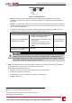
P Position duration Function Comments
Switch moved to P for less than
5 seconds, then released.
o
Displays production information for 5
seconds on the SetApp screen.
o
Displays error type indications (if exist)
for 5 seconds.
o
Activates the Wi-Fi access point for
connecting to the SolarEdge Inverter
SetApp
While the switch is in
P, all LEDs are ON
Switch moved to P for more than
5 seconds, then released.
Starts pairing
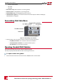
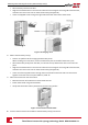
WARNING!
Upon Rapid Shutdown (PVRSS) the internal circuitry remains up, therefore the Primary Unit cover
must be opened only after shutting off the Primary Unit ON/OFF switch. This disables the DC
voltage inside the Primary Unit. Wait five minutes before opening the cover. Otherwise, there is a
risk of electric shock from energy stored in the capacitors.
LEDs
l LEDs:threeLEDsindicate,bycolorandstate(on/off/blinking
1
/flickering
2
/alternating
3
),different
systeminformation,suchaserrorsorperformanceindications.
Generally,themainLEDindicationsare:
l BlueON-theinverteriscommunicatingwiththemonitoringplatform
l GreenON-thesystemisproducing
l Greenblinking-ACisconnectedbutthesystemisnotproducing
l RedON-systemerror
1
Blinking = Turns ON and OFF for the same duration
2
Flickering = Turns ON for 100 mS and turns OFF for 5 seconds
3
Alternating = Alternate LEDs flash
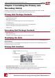
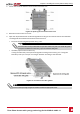
Chapter 3: Installing the Primary and Secondary Unit(s)
Three Phase Inverter with synergy technology Guide MAN-01-00401-1.1
22