
Installation Manual

NOTE
l Use at least 11 AWG/ 4 mm² DC cables.
l The total conductor length of the string (excluding power optimizers’ conductors; including home
runs and necessary extensions between optimizers) should not exceed:
o
For inverter models SE14.4K and SE33.3K - 2300 ft./ 700 m from DC+ to DC- of the inverter
IMPORTANTSAFETYFEATURE
l For a compliant PV Rapid Shutdown (PVRSS) installation, use no more than 30 optimizers per
string.
l Enabling PVRSS from the inverter menu is only required if the installed optimizers were
manufactured before 2015, otherwise it is enabled by default.
NOTE
The DC bus of each unit is separate and not shared for all units. Therefore in addition to following the
inverter design rules, each unit should follow the unit design rules as detailed in the Technical
Specifications.
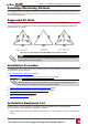
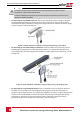
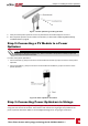
1. ConnecttheMinus(-)outputconnectorofthestring’sfirstpoweroptimizertothePlus(+)output
connectorofthestring’ssecondpoweroptimizer.
2.
Connecttherestofthepoweroptimizersinthestringinthesamemanner.
Figure 9: Power optimizers connected in series
3.
Ifyouintendtomonitortheinstallation,usingtheSolarEdgemonitoringplatform,recordthe
physicallocationofeachpoweroptimizer,asdescribedinProvidingInstallationInformationonpage49.
WARNING!
Input and output connectors are not watertight until mated. Open connectors should be mated to
each other or plugged with appropriate watertight caps.
Les connecteurs d’entrée et sortie ne sont pas étanches jusqu'à ce qu’ils soient accouplés. Les
connecteurs doivent être accouplés ou fermés avec des terminaux étanches.
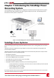
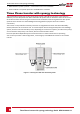
Three Phase Inverter with synergy technology Guide MAN-01-00401-1.1
19
Step 3: Connecting Power Optimizers in Strings