
Installation Manual
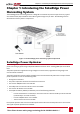
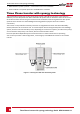
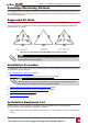
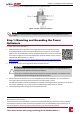
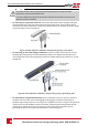
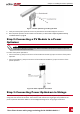
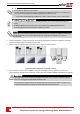

Figure 7: Power optimizer grounding terminal
5. Verifythateachpoweroptimizerissecurelyattachedtothemodulesupportstructure.
6. Recordpoweroptimizerserialnumbersandlocations,asdescribedinReportingandMonitoring
InstallationDataonpage48
Step 2: Connecting a PV Module to a Power
Optimizer
NOTE
Images are for illustration purposes only. Refer to the label on the product to identify the plus and
minus input and output connectors.
Foreachofthepoweroptimizers:
l ConnectthePlus(+)outputconnectorofthemoduletothePlus(+)inputconnectorofthepower
optimizer.
l ConnecttheMinus(-)outputconnectorofthemoduletotheMinus(-)inputconnectorofthe
poweroptimizer.
Figure 8: Power optimizer connectors
Step 3: Connecting Power Optimizers in Strings
Youcanconstructparallelstringsofunequallength,thatis,thenumberofpoweroptimizersineach
stringdoesnothavetobethesame.Theminimumandmaximumstringlengthsarespecifiedinthe
poweroptimizerdatasheets.RefertotheSolarEdgeSiteDesignerforstringlengthverification.
Chapter 2: Installing the Power Optimizers
Three Phase Inverter with synergy technology Guide MAN-01-00401-1.1
18