SolarEdge GSM Installation Guide Version 1.
About This Guide About This Guide SolarEdge offers the GSM communication option for connection of the SolarEdge inverter to the SolarEdge monitoring server. This guide assumes that the SolarEdge power harvesting system is already installed and commissioned. For additional information about how to install and commission the SolarEdge power harvesting system, refer to the relevant installation guide.
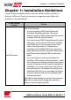
Chapter 1: Installation Guidelines Chapter 1: Installation Guidelines Inverters may be supplied with or without a GSM modem, and with or without a SIM card. Check your inverter configuration and follow the guidelines in the table below: If your inverter includes: Do this: One of the following: o If you purchased a GSM Cellular Modem kit including a SolarEdge data plan - Mount the antenna, install the GSM modem and SIM card and configure GSM, as described herein.
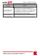
Chapter 1: Installation Guidelines If your inverter includes: Do this: A built-in GSM modem without a SIM card Insert a SIM card and configure the data plan as described herein. A data plan with SIM card is available from SolarEdge, or you may use your own plan (refer to the requirements in "Guidelines for installing a nonSolarEdge SIM Card" on the next page). A built-in GSM with a SIM card (data plan) Mount the supplied antenna as described herein. No configuration is required.
Chapter 1: Installation Guidelines Guidelines for installing a non-SolarEdge SIM Card Activating and using the GSM connection requires a SIM card (purchased separately from a SIM provider), which is inserted into a designated slot on the GSM modem. A SIM card is required in each GSM modem. If using a non- SolarEdge SIM card: l Calculate the data required (refer to Technical Specifications on page 26).
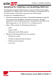
Chapter 1: Installation Guidelines When using multiple SolarEdge inverters in the same site , depending on the system operation mode (high or low bandwidth), a GSM modem must be installed as follows: l Low bandwidth - in each inverter l High bandwidth (up to 32 devices) - in one device (master inverter) Figure 1: GSM modem low BW mode connection diagram Figure 2: GSM modem high BW mode connection diagram GSM Installation Guide MAN-01-00248-1.
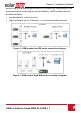
Chapter 2: System Compatibility Check and Upgrade Chapter 2: System Compatibility Check and Upgrade Hardware Requirements To use the GSM communication option, the communication board must include a designated modem connector, as shown in the following figure. If required, replace the communication board using the kit available from SolarEdge.
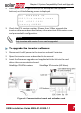
Chapter 2: System Compatibility Check and Upgrade 2. Short-press the LCD light button(in HD-Wave press the up/down buttons) until the following screen is displayed. ID: ######## ## DSP1/2:x.xxxx/x.xxxx CPU :0003.1600 Country:XXXXX 3. Check the CPU version number. If lower than 3.16xx, upgrade the inverter software as described below; otherwise close the inverter cover and proceedwith configuration. NOTE Only inverters with version 3.xxxx can be upgraded. To upgrade the inverter software: 1.
Chapter 2: System Compatibility Check and Upgrade 4. Turn the AC ON. WARNING! ELECTRICAL SHOCK HAZARD. Do not touch uninsulated wires when the inverter cover is removed. 5. If upgrade is required, it starts automatically. Wait for the message "Done" to be displayed on the LCD. 6. Verify the correct version as described above. 7. Remove the card from the inverter. 8 GSM Installation Guide MAN-01-00248-1.
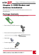
Chapter 3: GSM Modem and Antenna Installation Chapter 3: GSM Modem and Antenna Installation This chapter describes how to install a GSM modem and antenna in a SolarEdge device. Package Contents l GSM modem (optionally including a SolarEdge SIM card) l Plastic holder (for 1Ph/3Ph inverters) l Antenna and mounting clip with antenna cable l Cable holder l Firmware upgrade card l Tie-wrap (for HD-Waave inverter) GSM Installation Guide MAN-01-00248-1.
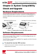
Chapter 3: GSM Modem and Antenna Installation Installing the Antenna and Cable 1. Connect the antenna to the mounting clip, and tighten by screwing the antenna to the clip. 2. Attach the mounting clip with the antenna vertically to the top of the inverter. You may attach the clip to the heat sink fins or the inverter side. Figure 5: Antenna mounted on the inverter If not mounting the antenna on the inverter, install the clip on the wall using two screws (not supplied).
Chapter 3: GSM Modem and Antenna Installation 3. Route the antenna cable along the inner fins or the inverter side, in the bracket. Make sure the cable is not hanging loose outside the inverter enclosure. 1Ph/3Ph inverter SolarEdge 1Ph inverter (HD-Wave) Figure 6: Routing the antenna cable 4. Open the gland numbered 1 at the bottom of the inverter. Figure 7: Inverter communication glands 5.
Chapter 3: GSM Modem and Antenna Installation 7. Insert the rubber seal with the cable into the gland body and reconnect the gland to the inverter. Tighten the sealing gland. 8. Pull the excess cable into the inverter so that the cable can be attached to the inverter communication board (see Figure 13). The cable connects to the GSM modem as described in the next section.
Chapter 3: GSM Modem and Antenna Installation To Install the modem in the SolarEdge 1Ph/3Ph inverters: 1. Loosen the upper-right screw attaching the communication board to the standoff. Figure 10: The communication board 2. Attach the supplied holder to the communication board and use the removed screw to fasten the holder to the board. Figure 11: The holder installed on the communication board GSM Installation Guide MAN-01-00248-1.
Chapter 3: GSM Modem and Antenna Installation 3. Locate the modem in its place on the communication board, as shown in Figure 12. Follow these guidelines: l Use the supplied holder to position the modem with the correct orientation and stabilize it l Plug in the modem making sure that all pins are correctly positioned in the modem connector, and no pins are left out of the connector. l Make sure that the modem is firmly in place. Figure 12: Installing the GSM modem on the holder 4.
Chapter 3: GSM Modem and Antenna Installation 6. Turn the AC ON. WARNING! ELECTRICAL SHOCK HAZARD. Do not touch uninsulated wires when the inverter cover is removed. 7. Check that all the GSM modem LEDs are lit. If not, refer to Troubleshooting on page 21. Figure 14: GSM modem LEDs GSM Installation Guide MAN-01-00248-1.
Chapter 3: GSM Modem and Antenna Installation To Install the modem in the SolarEdge 1Ph inverter (HD-Wave): 1. Locate the modem in its place on the communication board. Make sure that the modem is firmly in place (see Figure 15). 2. Connect the antenna cable to the modem and tighten manually. 3. Use the tie-wrap to fasten the modem to the communication board. Figure 15: Installed modem 4. Verify that the ON/OFF switch and Safety Switch (if installed) are OFF. 5. Turn the AC ON.
Chapter 4: Configuring GSM Communication Chapter 4: Configuring GSM Communication This chapter describes how to activate the GSM modem (if using a nonsolarEdge SIM card), configure the inverter to use GSM communication, verify the connection and troubleshoot problems. Configuring the Inverter 1. Verify that the inverter ON/OFF switch is OFF. 2. Enter the inverter Setup mode: l SolarEdge 1Ph/3Ph inverters - Press the Enter button for 5-10 seconds and release. Enter the password 12312312.
Chapter 4: Configuring GSM Communication 2. Select Server è Cellular. LAN RS485 Zigbee Wi-Fi Cellular RS232 None 3. If you are using a non- SolarEdge SIM card: a. Select Communication è Cellular Conf. The following is displayed: Set APN Set User Set Password Data Set 18 Plan Name
Chapter 4: Configuring GSM Communication b. Select Data Plan to set the communication mode. The following options are displayed: Low High BW BW Low Bandwidth - This mode utilizes a data plan for low-cost monitoring. In this mode, the data is sampled every 15 minutes and the server connection is established every 4 hours . In a multiple inverter system, a GSM modem and a SIM card are required in every inverter. Configuring to Low BW is required in every inverter.
Chapter 4: Configuring GSM Communication c. Select the communication mode. NOTE If you selected High BW, you can later change to Low BW. If you selected Low BW, to change to High BW, contact SolarEdge Support. d. Do one of the following: l If you selected High BW, a message is displayed: Significant cost may be incurred. Proceed?. If you select yes, the modem immediately attempts to establish communication with the monitoring server.
Chapter 4: Configuring GSM Communication Verifying the Connection 1. Check the server communication status screen: Server:Cell MNO: Sig:5 Status: message> Server: The method of communication to the SolarEdge monitoring portal. Should display Cell. Status: Displays OK if the inverter established a successful physical connection to the GSM modem. S_OK: The last communication to the SolarEdge monitoring portal was successful.
Chapter 4: Configuring GSM Communication LCD Error Messages Error message Description Troubleshooting No modem detected The internal modem is Check that the GSM modem is installed not communicating properly: All the pins are inserted in the with the correct location and not shifted. communication board. No SIM Card The SIM card is not inserted or not recognized. Enter PIN Personal Identification Name (PIN ) code is pending. Enter APN The Access Point Name (APN) parameter is empty.
Chapter 4: Configuring GSM Communication Error message No signal Description No GSM signal is received. Troubleshooting o Check that the cable is connected properly to both modem and antenna. o Check for any damage to the cable or connectors. o Try relocating the antenna. o Check that there is cellular coverage in your area. Activate Plan Data plan was not selected. Select a data plan as described in Configuring the Inverter on page 17.
Chapter 4: Configuring GSM Communication Error message Description Troubleshooting Replace the SIM card. NOTE SMS blocked The SIM card does not support SMS capability Replacing a SIM card requires system reconfiguration and activation. If the replaced SIM card was configured to Low BW, the new SIM can only be set to Low BW. Activate the modem manually: Unidentified # The mobile number is blocked or incorrectly decoded.
Chapter 4: Configuring GSM Communication Modem LED Indications LED functionality All LEDs are OFF Description The modem is not connected properly Troubleshooting Check that the modem is installed properly: All the pins are inserted in the correct location and not shifted. The modem is damaged Contact SolarEdge support The modem power LED is ON, but one or more of the other LEDs is OFF The modem is damaged Contact SolarEdge support GSM Installation Guide MAN-01-00248-1.
Appendix A: Technical Specifications Appendix A: Technical Specifications GSM modem for US systems: DATA PLAN (for Non-SolarEdge High Bandwidth Low Bandwidth SIM cards) Number of Inverters Monitored With a Single GSM Kit Up to 32 1 Data sampled Data sampled every 5 minutes every 15 minutes and sent to and sent to SolarEdge server SolarEdge server continuously every 4 hours Monitoring Monthly Data - per Inverter 7.8 2.6 MB Monthly Data - per Optimizer 0.15 0.
Appendix A: Technical Specifications Antenna Included, 2dBi outdoor; Dual band antenna: 824-960 MHz / 1710-2170 MHz Maximum output power 850 MHz band 33 dBm Maximum output power 1900 MHz band 30 dBm Typical -109 dBm Receiver Input Sensitivity (Downlink RF level @ BER Class II < 2.4 % ) Standard Compliance Emissions and Radio FCC CFR Title 47 Part 15 Class B, Part 15.247 Installation Specifications Dimensions (L x W) 3.55 x 1.35 / 90.5 x 34.
Appendix A: Technical Specifications GSM modem for worldwide systems: DATA PLAN (for Non-SolarEdge SIM cards) Number of Inverters Monitored With a Single GSM Kit Monitoring High Bandwidth Low Bandwidth Up to 32 1 Data sampled every 5 minutes and sent to SolarEdge server continuously Data sampled every 15 minutes and sent to SolarEdge server every 4 hour Unit Monthly Data - per Inverter 7.8 2.6 MB Monthly Data - per Optimizer 0.15 0.05 MB Monthly Data - per Production Meter 0.3 0.
Appendix A: Technical Specifications Antenna Included, 2dBi outdoor; Dual band antenna: 824-960MHz / 1710-2170MHz Maximum output power: 900 MHz band 33 dBm Maximum output power: 1800 MHz band 30 dBm Maximum output power: 2100 MHz band 24 dBm Receiver Input Sensitivity (Downlink RF level @BER Class II < 2.4 % ) Typical. -109 dBm Standard Compliance Emissions and Radio EN 301-489-1, EN 301-489-7, EN 301-511 Installation Specifications Dimensions (L x W) Operating Temperature 90.5 x 34.5 / 3.