
Install Manual
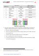
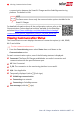

Table Of Contents
- Disclaimers
- Revision History
- Contents
- HANDLING AND SAFETY INSTRUCTIONS
- RISK OF FIRE AND ELECTRIC SHOCK PREVENTION IMPORTANT SAFETY INSTRUCTIONS
- Smart EV Charging Safety Instructions
- Chapter 1: Introduction to Smart EV Charger
- Chapter 2: Connectors and Interfaces
- Chapter 3: Configuring and Using Smart EV Charger with mySolarEdge
- Chapter 4: Charging Instructions
- Chapter 5: Professional Installer- Connecting the AC Directly to the Smart EV Charger
- Required Equipment
- Main Procedure
- Grid Connection Guidelines
- Setting the Circuit Breaker Ratings
- Supported AC Grids
- Removing the Smart EV Charger Covers
- Disconnecting the AC Plug
- Directly Connecting the AC Grid to the Smart EV Charger
- Connecting the Smart EV Charger to the Single phase inverter with HD-Wave tec...
- Closing the Smart EV Charger Covers
- Chapter 6: Professional Installer - Setting Up Communication
- Chapter 7: Processional Installer - Configuring and Using Smart EV Charger with SetApp
- Chapter 8: Errors and Troubleshooting
- Appendix A: Professional Installer - Connecting the Smart EV Charger to an Energy Meter
- Mechanical Specifications
- Technical Specifications - Smart EV Charger (North America)
- Support Contact Information

Appendix A: Professional Installer - Connecting
the Smart EV Charger to an Energy Meter
This section provides instructions for connecting the Smart EV Charger to an Energy
Meter. An Energy Meter is required for Smart Energy Management applications, such as
controlled Excess Solar charging.
To install the Energy Meter, refer to the installation guide supplied with it:
Energy Meter DIPSwitches
The following sections explain the DIPSwitches IDs and termination.
Energy Meter ID DIP Switches
The IDDIPswitches are used to set the Modbus address of the meter. The addressing
options are listed in the table below. See the figure
ID and termination DIP switches
on
page 50 for switch direction guidelines.
Table 1: Energy Meter ID DIP Switches
Modbus Address ID 1 ID 2 ID 3
0 Down Down Down
1 Up Down Down
2 Down Up Down
3 Up Up Down
4 Down Down Up
5 Up Down Up
6 Down Up Up
7 Up Up Up
Energy Meter Termination DIPSwitches
The Termination DIPswitches are used to configure RS485 wiring termination. The
termination options are listed in the table below. See the figure
ID and termination DIP
switches
on page 50 for switch direction guidelines and refer to
Table 1
.
Smart EV Charger Installation MAN-01-00657-1.0
49 Appendix A: Professional Installer - Connecting the Smart EV Charger
to an Energy Meter