
Install Manual
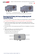
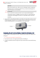
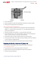
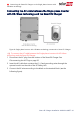
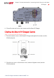
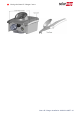
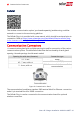

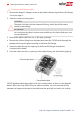
Table Of Contents
- Disclaimers
- Revision History
- Contents
- HANDLING AND SAFETY INSTRUCTIONS
- RISK OF FIRE AND ELECTRIC SHOCK PREVENTION IMPORTANT SAFETY INSTRUCTIONS
- Smart EV Charging Safety Instructions
- Chapter 1: Introduction to Smart EV Charger
- Chapter 2: Connectors and Interfaces
- Chapter 3: Configuring and Using Smart EV Charger with mySolarEdge
- Chapter 4: Charging Instructions
- Chapter 5: Professional Installer- Connecting the AC Directly to the Smart EV Charger
- Required Equipment
- Main Procedure
- Grid Connection Guidelines
- Setting the Circuit Breaker Ratings
- Supported AC Grids
- Removing the Smart EV Charger Covers
- Disconnecting the AC Plug
- Directly Connecting the AC Grid to the Smart EV Charger
- Connecting the Smart EV Charger to the Single phase inverter with HD-Wave tec...
- Closing the Smart EV Charger Covers
- Chapter 6: Professional Installer - Setting Up Communication
- Chapter 7: Processional Installer - Configuring and Using Smart EV Charger with SetApp
- Chapter 8: Errors and Troubleshooting
- Appendix A: Professional Installer - Connecting the Smart EV Charger to an Energy Meter
- Mechanical Specifications
- Technical Specifications - Smart EV Charger (North America)
- Support Contact Information

Cellular
This wireless communication option (purchased separately) enables using a cellular
network to connect to the monitoring platform.
The Cellular Plug-in is provided with a user manual, which should be reviewed prior to
connection. Refer to https://www.solaredge.com/sites/default/files/se-cellular-plug-
in-for-inverters-with-setapp-installation-guide.pdf
Communication Connectors
A communication gland with multiple openings is used for connection of the various
communication options. The table below describes the functionality of each gland
opening. Unused openings should remain sealed.
Opening for cable size (diameter) Connection type
2.5 - 5 mm RS485
4.5 - 7 mm, with cut
Ethernet (CAT5/6)
2 - 4 mm, with cut
Cable for external wireless or cellular
communication
Figure 9: Communication Gland
The communication board has a standard RJ45 terminal block for Ethernet connection
and a 6-pin terminal block for RS485 connection.
The CellularPlug-in can be connected to the communication board for optional
wireless connection.
Smart EV Charger Installation MAN-01-00657-1.0
37 Communication Connectors