
Install Manual
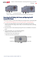
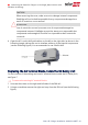
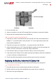
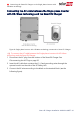
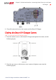
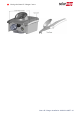

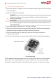
Table Of Contents
- Disclaimers
- Revision History
- Contents
- HANDLING AND SAFETY INSTRUCTIONS
- RISK OF FIRE AND ELECTRIC SHOCK PREVENTION IMPORTANT SAFETY INSTRUCTIONS
- Smart EV Charging Safety Instructions
- Chapter 1: Introduction to Smart EV Charger
- Chapter 2: Connectors and Interfaces
- Chapter 3: Configuring and Using Smart EV Charger with mySolarEdge
- Chapter 4: Charging Instructions
- Chapter 5: Professional Installer- Connecting the AC Directly to the Smart EV Charger
- Required Equipment
- Main Procedure
- Grid Connection Guidelines
- Setting the Circuit Breaker Ratings
- Supported AC Grids
- Removing the Smart EV Charger Covers
- Disconnecting the AC Plug
- Directly Connecting the AC Grid to the Smart EV Charger
- Connecting the Smart EV Charger to the Single phase inverter with HD-Wave tec...
- Closing the Smart EV Charger Covers
- Chapter 6: Professional Installer - Setting Up Communication
- Chapter 7: Processional Installer - Configuring and Using Smart EV Charger with SetApp
- Chapter 8: Errors and Troubleshooting
- Appendix A: Professional Installer - Connecting the Smart EV Charger to an Energy Meter
- Mechanical Specifications
- Technical Specifications - Smart EV Charger (North America)
- Support Contact Information

3. Pull out the DIN- rail.
4. Insert a screwdriver into each AC terminal block and press to remove the cables.
5.
Remove the AC terminal blocks from the DIN-rail.
To install the new AC terminal blocks:
1. Snap the two new AC terminal blocks onto the DIN rail.Place the terminal block
labeled “L1” on the left side of each pair and “L2“ on the right and put back the
terminal block labeled “N".
2.
Snap the end-stops onto the DIN rail - one on each side of the DIN rail.
3. Insert a dedicated tool or a 3.6"/5mm flat-blade screwdriver into the opening and
rotate it counter-clockwise to unlock the clamp mechanism.
4. Press the latch with your finger to hold the clamp in the unlock position.
5. Fully insert the ACcables into the cable openings and slightly rotate the screwdriver
counter-clockwise to release the latch.
6. Check that all the terminal block wires are firmly and correctly connected .
Replacing the Bus Bar, inside the DC Safety Unit
For the location of the existing bus bars inside the DC Safety Unit, see
Figure 7
.
To replace the bus bar:
1. Unscrew the two screws connecting the bus bar to the board.
2. Replace with the new bus bar and tighten the screws with a screwdriver.
3. Reconnect the grounding wires.
Chapter 5: Professional Installer- Connecting the AC Directly to the Smart
EVCharger 32
Smart EV Charger Installation MAN-01-00657-1.0