
User Guide
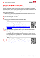
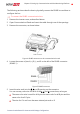
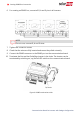
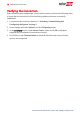
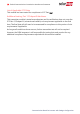
Table Of Contents

6.
For creating an RS485 bus, connect all B, A and G pins in all inverters.
NOTE
Do not cross-connect B, A and G wires.
7. Tighten the connector screws.
8. Check that the wires are fully inserted and cannot be pulled out easily.
9.
Connect the RS485 connector to the RS485 port on the communication board.
10.
Terminate the first and last SolarEdge inverter in the chain. The inverter can be
terminated by switching on (up) the left DIPswitch on the communication board.
Figure 6: RS485 termination switch
Communication Board for Inverters with SetApp Configuration
13 Creating RS485 Bus Connection