
User Guide
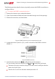
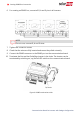
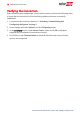
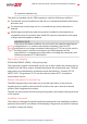
Table Of Contents

Figure 3: The RJ45 Ethernet connection
7. For the switch/router side, use a pre-crimped cable or use a crimper to prepare an
RJ45 communication connector: Insert the eight wires into the RJ45 connector in the
same order as above (see
Figure 2
).
8. Connect the cable RJ45 connector to the RJ45 port of the Ethernet switch or router.
You can connect more than one inverter to the same switch/router or to different
switches/routers, as needed. Each inverter sends its monitored data independently
to the SolarEdge monitoring platform.
9.
The inverter is configured by default to LAN. If reconfiguration is required:
a. Make sure the ON/OFF switch is OFF.
b. Turn ON the AC to the inverter by turning ON the circuit breaker on the main
distribution panel.
c.
Use the internal user buttons to configure the connection, as described in
Communication
on page 1.
NOTE
If your network has a firewall, you may need to configure it to enable
the connection to the following address:
Destination Address: prodssl.solaredge.com
TCP Port: 443 (for incoming and outgoing data)
10. Verify the connection, as described in
Verifying the Connection
on page 1.
Chapter 2: Setting Up Communication with the Monitoring Platform 10
Communication Board for Inverters with SetApp Configuration