
Specs
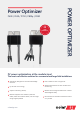

PV System Design Using
a SolarEdge Inverter
(6)(7)
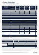
Three Phase
SE15K and
larger
Three Phase SE16K and larger Three Phase for 277/480V grid
Compatible Power Optimizers P600 P650 P600 P650 P730 P800p P850 P600 P650 P730 P800p P850
Minimum String Length
Power Optimizers 13
PV Modules 26
Maximum String Length
Power Optimizers 30
PV Modules 60
Maximum Power per String 11250
(8)
13500 12750
(9)
15300 W
Parallel Strings of Dierent Lengths or Orientations Ye s
(1)
P730 replaced the P700; P850 replaced the P800s; each pair can be used interchangeably and can be connected in the same ring.
(2)
Rated STC power of the module. Module of up to +5% power tolerance allowed.
(3)
For other connector types please contact SolarEdge.
(4)
Longer inputs wire length are available for use with split junction box modules. (For 0.9m/0.52ft order P730-xxxLxxx or P850-xxxLxxx.
For 1.3m/4.26ft order P850-xxxXxxx).
(5)
For ambient temperature above +70˚C / +158˚F power de-rating is applied. Refer to Power Optimizers Temperature De-Rating Application Note for more details.
Optimizer Model
(Typical Module
Compatibility)
P600
(for 2 x
60-cell PV
modules)
P650
(for 2 x
60-cell PV
modules)
P730
(1)
(for 2 x 72-cell
PV modules)
P800p
(for parallel
connection of
2x 96-cell 5’’
PV modules)
P850
(1)
(for series
connection of
2x high power or
bi-facial modules)
INPUT
Rated Input DC Power
(2)
600 650 730 800 850 W
Absolute Maximum Input Voltage
(Voc at lowe temperature)
96 125 83 120 Vdc
MPPT Operating Range 12.5 - 80 12.5 - 105 12.5 - 83 12.5 - 105 Vdc
Maximum Short Circuit Current (Isc) 10.25 11 11 14 12.5 Adc
Maximum Eciency 99.5 %
Weighted Eciency 98.6 %
Overvoltage Category II
OUTPUT DURING OPERATION (POWER OPTIMIZER CONNECTED TO OPERATING SOLAREDGE INVERTER)
Maximum Output Current 15 18 Adc
Maximum Output Voltage 85 Vdc
OUTPUT DURING STANDBY (POWER OPTIMIZER DISCONNECTED FROM SOLAREDGE INVERTER OR SOLAREDGE INVERTER OFF)
Safety Output Voltage per Power Optimizer 1 ± 0.1 Vdc
STANDARD COMPLIANCE
EMC FCC Part15 Class B, IEC61000-6-2, IEC61000-6-3
Safety IEC62109-1 (class II safety)
RoHS Yes
Fire Safety VDE-AR-E 2100-712:2013-05
INSTALLATION SPECIFICATIONS
Compatible SolarEdge Inverters
Three phase inverters
SE15K & larger
Three phase inverters
SE16K & larger
Maximum Allowed Syem Voltage 1000 Vdc
Dimensions (W x L x H) 129 x 153 x 42.5 / 5.1 x 6 x 1.7
129 x 153 x 49.5 /
5.1 x 6 x 1.9
129 x 168 x 59 /
5.1 x 6.61 x 2.32
129 x 162 x 59 /
5.1 x 6.4 x 2.32
mm / in
Weight (including cables) 834 / 1.8 933 / 2.1 1019 / 2.2 1064 / 2.3 gr / lb
Input Connector
(3)
MC4 MC4 Dual Input
(7)
MC4
Input Wire Length 0.16 / 0.52
0.16 , 0.9
(4)
/
0.52, 2.95
(4)
0.16 / 0.52
0.16 , 0.9
(4)
, 1.3
(4)
/
0.52 , 2.95
(4)
, 4.26
(4)
m/ft
Output Connector MC4
Output Wire Length
Portrait Orientation: 1.2 / 3.9
Landscape Orientation: 1.8 / 5.9
Portrait Orientation:
1.2 / 3.9
Landscape Orientation:
2.1 / 6.9
Portrait Orientation:
1.2 / 3.9
Landscape Orientation:
1.8 / 5.9
Portrait Orientation:
1.2 / 3.9
Landscape Orientation:
2.1 / 6.9
m / ft
Operating Temperature Range
(5)
-40 - +85 / -40 - +185 ˚C / ˚F
Protection Rating IP68 / NEMA6P
Relative Humidity 0 - 100 %
Power Optimizer
P600 / P650 / P730 / P800p / P850
© SolarEdge Technologies Ltd. All rights reserved. SOLAREDGE, the SolarEdge logo, OPTIMIZED BY SOLAREDGE are trademarks or registered trademarks of SolarEdge Technologies, Ltd.
All other trademarks mentioned herein are trademarks of their respective owners. Date: 03/2019/V02/ENG ROW. Subject to change without notice.
(6)
P600, P650 and P730 can be mixed in one ring. It is not allowed to mix P600/P650/P730 with P800p/P850 or to mix P600/P650/P730/P800p/P850 with P300/P370/P500/P404/P405/P505 in one ring.
(7)
In a case of odd number of PV modules in one ring it is allowed to inall one P600/P650/P730/P800p/P850 power optimizer connected to one PV module. When connecting a single module to the P800p
seal the unused input connectors with the supplied pair of seals.
(8)
For SE27.6K, SE55K, SE82.8K: It is allowed to inall up to 13,500W per ring when 3 rings are connected to the inverter and when the maximum power dierence between the rings
is up to 2,000W; inverter max DC power: 37,250W.
(9)
For inverters for 277/480V grid: It is allowed to inall up to 15,000W per ring when 3 rings are connected to the inverter (3 rings per unit when using SE66.6K and SE100K)
and when the maximum power dierence between the rings is up to 2,000W; inverter max DC power: 45,000W.