
Site Manager Manual

23
SolarEdge Site Designer
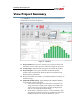
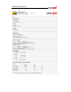
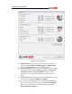
Figure 15 – Project report
1 User contact information and SolarEdge logo – this appears at the top
of every page in the report.
2 To: customer contact information.
3 Project: project name, description and creation date.
4 Location: system location.
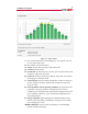
5 System data: system STC power, max DC power at given location and
orientation, and inverter AC power.
6 PV Arrays: details of all the arrays defined: Array name, tilt, azimuth,
mounting type and module model.
7 Inverter design: inverter models and quantities, number of strings per
inverter and power optimizer quantity and configuration from each
array, per string.
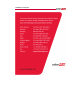
8 Power optimizer extreme operating conditions: the expected electric
parameters of the power optimizer configuration under extreme
conditions at the selected location and orientation, displayed next to the
power optimizer limitations. A green checkmark is displayed next to
each valid parameter.
9 Energy estimation: graph displaying the estimated monthly energy
that the system will produce, including AC energy loss due to output
power clipping, if it occurs.
10 Bill of Materials: the part number and quantity of each SolarEdge
product needed for the design.