
Site Manager Manual

13
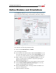
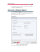
SolarEdge Site Designer
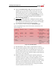
You also have the option of changing the following fields:
8 Edit the PV array name. This name will appear in the system
recommendation and in the system report, if you generate one.
9 If the desired module is not available, you can add a module by
pressing the Add icon . You can later edit or delete this location
using the corresponding icons (these icons appear only when using a
location you added). Added modules can be sent to SolarEdge for
inclusion in the Site Designer after verification. To send them select
Send/Send my database to SolarEdge from the main menu.
10 Change the Mounting of the system. This affects the modules’
temperature.
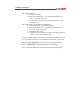
11 For a multi-facet system, or for a system with several module models,
add a PV Array for each additional orientation and module type. This
is done by pressing the Add icon at the top of the screen.
After all selections are made you may view the following two results
12 View the electrical parameters of a selected module, under both STC
conditions and extreme conditions at the selected location and
orientation.
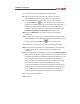
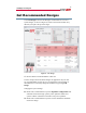
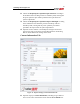
13 See all compatible power optimizers by pressing the Display optimizer
data, as shown in Figure 8. A green V marks power optimizers that are
compatible with the chosen modules and orientations. Hover over a red
X to understand why a certain power optimizer does not match, as
shown in Figure 8. Sometimes the application will allow connecting
more than one module to each power optimizer input. These
connections are indicated with the following notation after the power
optimizer model: axb; this means that a modules are connected to the
power optimizer input in parallel, and b modules are connected in
series. For parallel connection you will need to use a branch-cable.
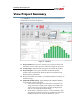
After entering all the information:
14 Press Next.