
Quick Installation Guide
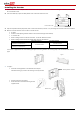
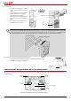

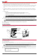
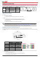
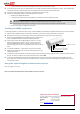
Table Of Contents
- SolarEdge Quick Installation Guide – North America

8
G
A (Data+)
B (Data-)
RS485-2 (not in use)
Connect the Ethernet connector to the RJ45 port on the inverter's communication board.
4 For the switch/router side, use a pre-crimped cable or use a crimper to prepare an RJ45 communication connector: Insert the eight wires
into the RJ45 connector, maintaining the same color coding and pinout on both sides of the Ethernet cable.
5 Connect the cable’s RJ45 connector to the RJ45 port of the Ethernet switch or router.
6 Inverters are configured by default to LAN. If reconfiguration is required:
Make sure the ON/OFF switch is OFF.
Turn ON the AC to the inverter by turning ON the circuit breaker on the main distribution panel.
WARNING!
ELECTRICAL SHOCK HAZARD. Do not touch uninsulated wires when the inverter cover is removed.
RISQUE D’ÉLECTROCUTION. Ne touchez pas les fils non isolés lorsque le couvercle de l'onduleur est retiré.
Use the user buttons to configure the connection.
Creating an RS485 connection
If a revenue grade meter is connected to your inverter, it uses the RS485 port and therefore an RS485 communication bus cannot be created.
1 Make sure that the ON/OFF switch at the bottom of the inverter is turned OFF, and the Safety Switch is turned OFF.
2 Remove the seal from one of the openings in communication gland #2 and insert the wire through the opening.
3 Pull out the 9-pin RS485/RS232 terminal block connector, and loosen the
screws of pins B, A and G on the left of the RS-485 terminal block.
4 Insert the ends of wires into the G, A and B pins. Use four- or six-wire
twisted pair cable for this connection. You can use any color wire for
each of the A, B and G connections, as long as the same color wire is
used for all A pins, the same color for all B pins and the same color for all
G pins.
5 For creating an RS485 bus - connect all B, A and G pins in all inverters.
6 Tighten the terminal block screws, and push it firmly all the way into the
communication board.
7 Terminate the first and last inverters in the chain by switching a termination Dip-switch inside the inverter to ON (move the left switch to
the top). The switch is located on the communication board and is marked SW7.
8 To connect to the SolarEdge monitoring portal, designate a single inverter as the connection point between the RS485 bus and the
monitoring portal. This inverter will serve as the master inverter. Connect the master to the SolarEdge monitoring portal via one of the
communication options.
Using the optional ZigBee communication option
Refer to the ZigBee kit user manual.
Refer to the SolarEdge Installation Guide for detailed installation and safety instructions.
Support and Contact Information
If you have technical problems concerning our products, please contact us:
USA and Canada:
+1 (0) 877 360 5292
Worldwide:
+972 (0) 73 240-3118
Fax:
+1 (0) 530 273-2769
Email to support@solaredge.us