
Quick Installation Guide
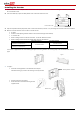
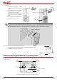

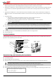
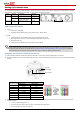
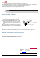
Table Of Contents
- SolarEdge Quick Installation Guide – North America

7
Setting up Communication
Two communication glands are used for connection of the various inverter communication options. Each gland has three openings. The table
below describes the functionality of each opening. Unused openings should remain sealed.
Gland#
Opening
Functionality
Cable Size
(diameter)
1(PG 16)
One small
External antenna cable
2-4 mm
Two large
Ethernet connection
(CAT5/6), ZigBee, CDMA
4.5-7 mm
2 (PG 13.5)
All three
RS485, power reduction
2.5-5 mm
Cable Specifications
Ethernet:
Cable type – CAT5/CAT6
Maximum distance between the inverter and the router – 100 m/ 330 ft.
RS485:
Cable type: Min. 3-wire shielded twisted pair (a 4-wire cable may be used)
Wire cross-section area: 0.2- 1 mm²/ 24-18 AWG (a CAT5 cable may be used)
Maximum nodes: 32
Maximum distance between first and last devices: 1 km /3300 ft.
Creating an Ethernet (LAN) connection
1 Make sure that the ON/OFF switch at the bottom of the inverter is turned OFF, and the Safety Switch is turned OFF.
2 Remove the plastic seal from the large opening that has a cut in communication gland #1 and insert an Ethernet CAT5/6 cable through the
opening.
RJ45 Pin #
Color
T568B Standard
T568A Standard
1
White/Orange
White/Green
2
Orange
Green
3
White/Green
White/Orange
4
Blue
Blue
5
White/Blue
White/Blue
6
Green
Orange
7
White/Brown
White/Brown
8
Brown
Brown
3 Use a pre-crimped cable to connect via gland no.1 to the RJ45 plug on the inverter's communication board, or, if using a spool of cable,
connect as follows:
Insert the cable through gland no.1.
Insert the eight wires into an RJ45 connector, as described in the figure above.
Use a crimping tool to crimp the connector.
NOTE:
If using a cable longer than 10 m/33 ft in areas where there is a risk of induced voltage surges by lightning, it is recommend to use
external surge protection devices. For details refer to: http://www.solaredge.us/files/pdfs/lightning_surge_protection.pdf. If grounded
metal conduit are used for routing the communication wires, there is no need for a lightning protection device.
Communication glands
Mini USB
Ethernet (RJ45)
RS232/RS485