
Quick Installation Guide
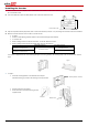
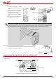

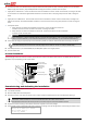
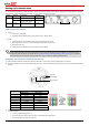
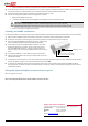
Table Of Contents
- SolarEdge Quick Installation Guide – North America

5
3 Connect the DC wires, and check that they are fully inserted and cannot be pulled out easily. If the Safety Switch has a pre-assembled
RGM (in single phase inverters), flip the RGM plate before making the connections, and then return the plate:
Single phase 3-7.6kW inverter - Connect the DC wires from the PV installation to the DC+ and DC- terminal blocks, according to the labels
on the terminals. Use a standard straight-bladed screwdriver to connect the wires to the spring-clamp terminals. Refer to the figures
above.
Single phase 10-11.4kW inverter - Connect the DC wires from the PV installation to the DC+ and DC- terminal blocks, according to the
labels on the terminals. Use standard flat-blade screwdriver to connect the wires to the spring-clamp terminals as shown in the figures
above.
Three phase inverter
Safety switch version without terminal blocks on the DC side - Connect the DC wires from the PV
installation to the DC+ and DC- terminals on the switch, according to the labels.
Safety switch version with terminal blocks on the DC side - Connect the DC wires from the PV installation
to the DC+ and DC- terminal blocks.
CAUTION:
Ensure that the Plus (+) wire is connected to the Plus (+) terminal and that the Minus (-) wire is connected to the Minus (-) terminal.
Veillez à ce que le câble Plus (+) soit connecté au terminal Plus (+) et que le câble Minus (-) soit connecté au terminal Minus (-).
4 If more than two strings are required, they can be connected in parallel in an external combiner box before connecting to the switch.
NOTE:
If more than two strings are connected each should be properly fused on both DC+ and DC- according to NEC690.35(B).
5 If the Safety Switch has a pre-assembled RGM, flip the RGM plate upwards to its original position.
6 Close the switch cover.
Inverter Interfaces
The following figure shows the inverter connectors and components, located at the bottom of the inverter. The ON/OFF switch and the LCD
light button may vary depending on the inverter model:
Commissioning and Activating the Installation
1 Verify that the inverter ON/OFF switch is OFF.
2 Turn ON the AC breaker.
3 Move the Safety Switch to the ON position.
4 Remove the inverter cover: Open the inverter cover’s six Allen screws and carefully pull the cover vertically before lowering it.
WARNING!
ELECTRICAL SHOCK HAZARD. Do not touch uninsulated wires when the inverter cover is removed.
RISQUE D’ÉLECTROCUTION. Ne touchez pas les fils non isolés lorsque le couvercle de l'onduleur est retiré.
5 Activate the inverter according to the activation instructions supplied in the inverter package.
6 Verify that the inverter is configured to the proper country or grid setting: Press the LCD light button until reaching the ID status screen:
I D : # # # # # # # # # #
D S P 1 / 2 : 1 . 0 2 1 0 / 1 . 0 0 3 4
C P U : 0 0 0 2 . 0 1 1 1
C o u n t r y : U S A 2
DC conduit entry
LCD panel and LEDs
ON/OFF switch
LCD light button
Sealed plug
AC conduit entry
Communication glands
Fan
ON/OFF
Switch
LCD light
button