
P400 Specs


Power Optimizer
P370 / P401 / P404 / P405 / P485 / P500 / P505
© SolarEdge Technologies, Ltd. All rights reserved. SOLAREDGE, the SolarEdge logo, OPTIMIZED BY SOLAREDGE are trademarks or registered trademarks of SolarEdge Technologies, Inc. All other trademarks mentioned herein
are trademarks of their respective owners. Date: 06/2020/V02/ENG ROW. Subject to change without notice.
(1) Rated power of the module at STC will not exceed the optimizer “Rated Input DC Power”. Modules with up to +5% power tolerance are allowed.
(2) For other connector types please contact SolarEdge.
(3) For dual version for parallel connection of two modules use the P485. In the case of an odd number of PV modules in one string, installing one P485 dual version power optimizer connected to
one PV module is supported. When connecting a single module, seal the unused input connectors using the supplied pair of seals.
OPTIMIZER MODEL
(typical module compatibilty)
P370
(60/72 Cell
modules)
P401
(For high
power
60/72-cell
modules)
P404
(for 60/72-
cell short
strings)
P405
(for
high-voltage
modules)
P485
(for
high-voltage
modules)
P500
(for 96-cell
modules)
P505
(for higher
current
modules)
UNIT
INPUT
Rated Input DC Power
(1)
370 400 405 405 485 500 505 W
Absolute Maximum Input Voltage
(Voc at lowest temperature)
60 80 125 80 83 Vdc
MPPT Operating Range 8 - 60 12.5 - 80 12.5 - 105 8 - 80 12.5-83 Vdc
Maximum Short Circuit Current (Isc) 11 11.75 11 10.1 14 Adc
Maximum Efciency 99.5 %
Weighted Efciency 98.8 %
Overvoltage Category II
OUTPUT DURING OPERATION
(
POWER OPTIMIZER CONNECTED TO OPERATING SOLAREDGE INVERTER
)
Maximum Output Current 15 Adc
Maximum Output Voltage 60 85 60 85 Vdc
OUTPUT DURING STANDBY
(
POWER OPTIMIZER DISCONNECTED FROM SOLAREDGE INVERTER OR SOLAREDGE INVERTER OFF
)
Safety Output Voltage per Power
Optimizer
1 ± 0.1 Vdc
STANDARD COMPLIANCE
EMC FCC Part15 Class B, IEC61000-6-2, IEC61000-6-3
Safety IEC62109-1 (class II safety), UL1741
RoHS Yes
Fire Safety VDE-AR-E 2100-712:2013-05
INSTALLATION SPECIFICATIONS
Maximum Allowed System Voltage 1000 Vdc
Dimensions (W x L x H)
129 x 153 x 27.5
/ 5.1 x 6 x 1.1
129 x 153 x29.5
/ 5.08 x6.02 x
1.16
129 x 89 x
42.5 / 5.1 x 3.5
x 1.7
129 x 90 x 49.5 / 5.1 x 3.5 x 1.9
129 x 153 x
33.5 / 5.1 x 6
x 1.3
129 x 162 x
59 / 5.1 x 6.4
x 2.3
mm
/ in
Weight (including cables) 655 / 1.5 775 / 1.7 845 / 1.9 750 / 1.7 1064 / 2.3 gr / lb
Input Connector MC4
(2)
Single or
Dual MC4
(2)(3)
MC4
(2)
Input Wire Length 0.16 / 0.52 m / ft
Output Connector MC4
Output Wire Length 1.2 / 3.9 m / ft
Operating Temperature Range -40 - +85 / -40 - +185 ˚C / ˚F
Protection Rating IP68
Relative Humidity 0 - 100 %
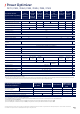
PV SYSTEM DESIGN USING A
SOLAREDGE INVERTER
(4)(5)
SINGLE PHASE
HD-WAVE
SINGLE PHASE THREE PHASE
THREE PHASE
FOR 277/480V
GRID
Minimum String Length
(Power Optimizers)
P370, P401, P500
(6)
8 16 18
P404, P405, P485, P505 6 14 (13 with SE3K
(7)
) 14
Maximum String Length (Power Optimizers) 25 50 50
Maximum Power per String 5700 5250 11250
(8)
12750
(9)
W
Parallel Strings of Different Lengths or Orientations Yes
(4) It is not allowed to mix P404/P405/P485/P505 with P370/P401/P500/P600/P650/P730/P801/P800p/P850/P950 in one string.
(5) For SE15k and above, the minimum DC power should be 11KW.
(6) The P370/P401/P500 cannot be used with the SE3K three phase inverter (available in some countries; refer to the three phase inverter SE3K-SE10K datasheet).
(7) Exactly 10 when using SE3K-RW010BNN4
(8) For the 230/400V grid: it is allowed to install up to 13,500W per string when the maximum power diference between each string is 2,000W.
(9) For the 277/480V grid: it is allowed to install up to 15,000W per string when the maximum power diference between each string is 2,000W