
Installation Manual

Chapter 4: Connecting Environmental Sensors (Optional)
Control and Communication Gateway Installation Guide - MAN-01-00132-1.2
30
► To connect an ambient or module temperature sensor to the power supply
and to the SolarEdge gateway:
The same power supply can be used for both sensors.
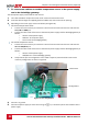
1 Use a flat screwdriver to open the sensor cover screws and remove the cover.
2 Insert the cable through the supplied gland and rubber seal, and into the sensor opening.
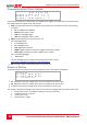
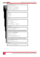
3 Depending on the sensor type, connect as follows (see Figure 18):
For ambient temperature sensor:
Connect the wires to the 3-pin connector: Loosen the screws and insert the wire ends into the
OUT, UB and GND pins.
Connect the other ends of the wires to the external power supply and the SolarEdge gateway as
follows:
o UB to V+ of the power supply
o GND to V- of the power supply
o Out to V2 of the SolarEdge gateway
For module temperature sensor:
Connect the wires to the 2-pin connector: Loosen the screws and insert the wire ends into the
UB and GND/OUT pins.
Connect the other ends of the wires to the external power supply and the SolarEdge gateway as
follows:
o UB to V+ of the power supply
o GND/OUT to I+ of the SolarEdge gateway
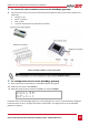
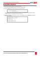
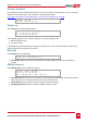
Verify that the pins are configured to -10 to 120C. If required, move the black covers to the
necessary configuration as shown in Figure 19.
Figure 19: Pin configuration
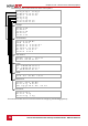
4 Connect I- to ground.
5 Connect the power supply to an AC source using the , N, L connection points at the bottom of the
power supply.
Black covers
Configurations