Disclaimers Disclaimers Important Notice Copyright © SolarEdge Inc. All rights reserved. No part of this document may be reproduced, stored in a retrieval system or transmitted, in any form or by any means, electronic, mechanical, photographic, magnetic or otherwise, without the prior written permission of SolarEdge Inc. This document is solely for the use of SolarEdge customers and employees. The material furnished in this document is believed to be accurate and reliable.
Table of Contents Table of Contents Disclaimers ......................................................................................................................... 1 Important Notice ...............................................................................................................1 Exclusion of Liability ...........................................................................................................1 FCC Compliance ..............................................................
Table of Contents Chapter 5: LCD – Status Screens and Setup Options .......................................................... 32 Status Screens ..................................................................................................................32 Initial Gateway Status.............................................................................................................. 32 ID Status .......................................................................................................
About This Guide About This Guide This user guide is intended for Photovoltaic (PV) system owners, installers, technicians, maintainers and integrators who use the SolarEdge power harvesting system. This guide describes the process of installing and configuring the SolarEdge Control and Communication gateway (also referred to as SolarEdge gateway). This guide assumes that the SolarEdge power harvesting system is already installed and commissioned.
Support and Contact Information Support and Contact Information If you have technical queries concerning our products, please contact us: Australia 1800 465 567 support@solaredge.net.au Belgium 0800 73041 support@solaredge.be France 0800 917410 support@solaredge.fr Germany +49 89-45459730 support@solaredge.de Italy 800 784 824 support@solaredge.it Japan +81.3.5530.9360 support@solaredge.jp APAC (Asia Pacific) support-asia@solaredge.com United Kingdom 0800 028 1183 support@solaredge.
Handling and Safety Instructions Handling and Safety Instructions During installation, testing and inspection, adherence to the following handling and safety instructions is mandatory. The following safety symbols may be used in this document. Familiarize yourself with the symbols and their meaning before installing or operating the system. WARNING! Denotes a hazard. It calls attention to a procedure that, if not correctly performed or adhered to, could result in injury or loss of life.
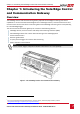
Chapter 1: Introducing the SolarEdge Control and Communication Gateway Chapter 1: Introducing the SolarEdge Control and Communication Gateway Overview The SolarEdge control and communication gateway expands the SolarEdge monitoring and control capabilities. It can be connected to SolarEdge and non-SolarEdge inverters, environmental sensors and revenue meters and can transfer the monitoring data to the SolarEdge monitoring server and optionally, to a non-SolarEdge logger.
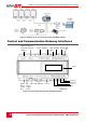
Chapter 1: Introducing the SolarEdge Control and Communication Gateway Figure 2: Example of sensor connection to the SolarEdge gateway Control and Communication Gateway Interfaces Optional Optional Antenna1 Antenna2 (ZigBee) Control RS485-1 SW1 RS485-2 RS232 USB SW2 LCD LEDs: DC Micro SD Ethernet Green (power Yellow supply Red input) Enter (3) Down (2) Up (1) Esc Sensors LCD Buttons Figure 3: Control and Communication Gateway Interfaces 8 Control and Communication Gateway Installation Guide - MA
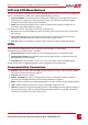
Chapter 1: Introducing the SolarEdge Control and Communication Gateway LCD and LCD-Menu Buttons The LCD screen displays status information of the SolarEdge gateway and various menus for configuration options. The LCD panel and buttons are used during the following processes: Operational Mode: The LCD panel allows checking that the gateway is working properly. Refer to Status Screens on page 32 for a description of this option.
Chapter 1: Introducing the SolarEdge Control and Communication Gateway Other Interfaces DC: used for the power supply input as described in Connecting the SolarEdge Gateway to AC on page 14. Sensors: enables connecting to external environmental sensors (refer to Chapter 4: Connecting Environmental Sensors (Optional) on page 22).
Chapter 2: Installing the SolarEdge Gateway Chapter 2: Installing the SolarEdge Gateway Safety CAUTION: For North America only: The product’s communication with external devices, must not use wires that span more than one building, as per the UL 60950-2 standard. Transport and Storage Transport the SolarEdge gateway in its original packaging, without exposing it to unnecessary shocks. If the original package is no longer available, use a similar box, which can be closed fully.
Chapter 2: Installing the SolarEdge Gateway Installation Guidelines The following requirements apply when locating and mounting the SolarEdge gateway: The SolarEdge gateway is suitable for mounting indoors only. For outdoor installation, use an external outdoor enclosure (not provided by SolarEdge) The SolarEdge gateway must always remain in an ambient temperature of -20°C (-4°F) to +60°C (140°F).
Chapter 2: Installing the SolarEdge Gateway Mounting and Connecting the SolarEdge Gateway The SolarEdge gateway can be installed on a wall or on a DIN rail. ► To mount the SolarEdge gateway on a wall: 1 Determine the mounting location. Leave clearance from all sides of the SolarEdge gateway for cover opening, cable connection and routing. 2 Open the clips at the rear of the gateway by pushing the clips outwards.
Chapter 2: Installing the SolarEdge Gateway 2 Hook the two lower clips of the SolarEdge gateway onto the lower edge of the DIN rail. 3 Press the SolarEdge gateway upwards and snap it into the upper edge of the DIN rail. When on the rail, the clip "grips" the rail on both the top and bottom lips of the rail.
Chapter 3: Connecting the SolarEdge Gateway to the SolarEdge Installation Chapter 3: Connecting the SolarEdge Gateway to the SolarEdge Installation Overview The SolarEdge control and communication gateway connects to the PV system installation using the RS485 communication option. The RS485 option enables creating a chain (bus) of up to 31 slave SolarEdge devices, connected to one master, which can be another SolarEdge device or the SolarEdge control and communication gateway.
Chapter 3: Connecting the SolarEdge Gateway to the SolarEdge Installation 2 Choose either RS485-1 or RS485-2 for connection. Connect the 3-pin terminal block to the designated port on the gateway. NOTE: RS485-1 is configured as SolarEdge device by default, therefore RS485-1 is recommended as the RS485 bus connection point. 3 If the gateway is at the end of the RS485 chain, terminate the gateway by switching a termination dipswitch to ON.
Chapter 3: Connecting the SolarEdge Gateway to the SolarEdge Installation 7 Loosen the screws of pins B, A and G on the left of the RS-485 terminal block: For inverter: RS485-1 pins (left-most) For SMI: RS485-1 (recommended, as this is the default configuration), or RS485-2 Screws G A RS485-2 (used in SMI only) B G A RS485-1 B Figure 10: RS485/RS232 8 Insert the ends of wires into the G, A and B pins shown above.
Chapter 3: Connecting the SolarEdge Gateway to the SolarEdge Installation 10 Tighten the terminal block screws. 11 Push the RS485 terminal block firmly all the way into the communication board. 12 Terminate the inverters/SMIs at the two ends of the chain by switching a termination dipswitch inside the inverter/SMI to ON (move the switch to the top). The switch is located on the communication board and is marked SW7.
Chapter 3: Connecting the SolarEdge Gateway to the SolarEdge Installation 3 Short-press the arrow buttons to scroll to the Communication menu. Press the Enter key to select it. 4 Select Server RS485-X Conf (X=1 or 2 depending on the specific physical port connection) to communicate with different external devices (SolarEdge inverters, revenue meters, non-SolarEdge loggers or non-SolarEdge inverters).
Chapter 3: Connecting the SolarEdge Gateway to the SolarEdge Installation RS485 Configuration Options In all configurations, use the following RS485 port configuration menus.
Chapter 3: Connecting the SolarEdge Gateway to the SolarEdge Installation Device ID: The device ID is used to set the SolarEdge gateway device ID (MODBUS ID) when connecting to an external master device (for example, a non-SolarEdge logger), or to set the ID of the external device (for example, revenue meter). Slave Detect: Is used to initiate automatic detection of the slave devices connected to this master gateway. The number next to the option is the number of devices that have been detected.
Chapter 4: Connecting Environmental Sensors (Optional) Chapter 4: Connecting Environmental Sensors (Optional) Overview The SolarEdge control & communication gateway supports up to three analog sensors.
Chapter 4: Connecting Environmental Sensors (Optional) Connecting Sensors to the SolarEdge Gateway For connection of the irradiance and temperature sensors available from SolarEdge refer to Sensor Connection Example on page 29. Sensors are directly connected to the SolarEdge gateway via the sensor interface connector. Use the supplied 7-pin terminal block. Figure 14 shows the location of the sensors connector on the gateway.
Chapter 4: Connecting Environmental Sensors (Optional) The 12V (pin7) can be used as the supply voltage to the sensor. Optionally, an external power supply can be connected to the sensors if a different input voltage to the sensor is required. For an example of sensor connection, refer to Sensor Connection Example on page 29.
Chapter 4: Connecting Environmental Sensors (Optional) The 12V (pin7) can be used as the supply voltage to the sensor. Optionally, an external power supply can be connected to the sensors if a different input voltage to the sensor is required. CAUTION! Excessive current on the sensor input can damage the SolarEdge gateway. Refer to input ranges specified in Appendix A: Technical Specifications on page 46.
Chapter 4: Connecting Environmental Sensors (Optional) Sensor Type: One of the following sensors: Sensor Type Description Unit Temp. Ambient Ambient temperature sensor measurement °C, °F Temp. Module Module temperature sensor measurement Wind Speed Wind speed sensor measurement m/s Wind Direction Wind direction sensor measurement degrees Irradiance Global Global horizontal irradiance W/m2 Irradiance Direct Direct irradiance Irradiance Diff.
Chapter 4: Connecting Environmental Sensors (Optional) ► To configure sensors in the SolarEdge gateway: NOTE: When using sensors provided by SolarEdge, enabling the sensors as described above automatically sets their configuration (available from SolarEdge gateway CPU version 2.07xx). If the CPU version is lower, configure the sensors as described below. Configure the working range of the sensor that covers the sensor specification. Refer to the table on page 22.
Chapter 4: Connecting Environmental Sensors (Optional) Example of Sensor Graph Configuration The following is an example of setting a temperature sensor with the following specifications: Measurement signal: 0..10V Measurement range: -10...+70°C The following graph shows the min. and max. values, and the focused (linear) area.
Chapter 4: Connecting Environmental Sensors (Optional) Sensor Connection Example This section describes how to connect three of the sensors available from SolarEdge to the Control & Communication Gateway. For their full specifications refer to http://www.solaredge.com/files/pdfs/products/inverters/se_sensor_datasheet.pdf (for other recommended sensors and suppliers refer to http://www.solaredge.com/articles/se-supporteddevices#environmental_sensors).
Chapter 4: Connecting Environmental Sensors (Optional) ► To connect an ambient or module temperature sensor to the power supply and to the SolarEdge gateway: The same power supply can be used for both sensors. 1 Use a flat screwdriver to open the sensor cover screws and remove the cover. 2 Insert the cable through the supplied gland and rubber seal, and into the sensor opening.
Chapter 4: Connecting Environmental Sensors (Optional) ► 1 To connect a solar irradiance sensor to the SolarEdge gateway: Connect the thin wires to the control and communication gateway sensors connector as follows (see Figure 20): Orange - to V1 Black - to Ground Red - to 12V Leave the thicker black wire (Shield) unconnected. Figure 20: Solar irradiance sensor connection NOTE: When configuring this sensor in the gateway, the type should be Irradiance Direct.
Chapter 5: LCD – Status Screens and Setup Options Chapter 5: LCD – Status Screens and Setup Options This chapter describes the LCD display of the SolarEdge control and communication gateway. The LCD screen displays status information of the gateway and various menus for configuration options. Status Screens During normal operation, pressing the Enter button turns the LCD backlight ON. Additional presses on the Enter button display the following screens one after the other.
Chapter 5: LCD – Status Screens and Setup Options Bit 4: The ping to google.com was OK. Bit 5: The ping to server1 was OK. Bit 6: The ping to server2 was OK. Bit 7: The ping to server3 was OK. Bit 8: Communication to the SolarEdge server is OK. Error message: Refer to Troubleshooting Ethernet Communication on page 44. IP Status This window describes the Ethernet configuration: IP, Mask, TCP gateway and MAC address of the gateway. I M G M P S K W A C 1 2 1 0 9 5 9 - 2 5 2 2 . . .
Chapter 5: LCD – Status Screens and Setup Options Communication Ports Status D R S 4 8 5 - 1 < S R S 4 8 5 - 2 < Z i g B e e < S e v P r o t # E > < S > < - - > < - - > < E > < M P S > < - # - > - > - > This window presents the communication port (RS485-1/2 or ZigBee), and the devices connected to them, with details about the number, type, and protocol.
Chapter 5: LCD – Status Screens and Setup Options Setup Menu Options This section describes basic gateway configuration options. 1 Verify that the SolarEdge gateway is connected to a power outlet. 2 Press the Enter button until the following message is displayed: P l e a s e e n t e r P a s s w o r d * * * * * * * * The gateway is now in Setup mode and all its LEDs are lit. The gateway automatically exits Setup mode if no buttons are pressed for more than 2 minutes.
Chapter 5: LCD – Status Screens and Setup Options The following shows a hierarchical tree of the menu options: L C P S D M I a o o e i a n n m w n s i f g m e s p n o u u r o l t r a g e n i c C o r s a y e n a m a t i a i c i s h n s h h a n < e n g > a t i o n n t r o l n c e i o n Language: E G S F I n e p r t g r a e a l m n n l Communication: S L R R Z W R e A S S i i S r N 4 4 g 2 v e C 8 5 8 5 B e F i 3 2 r o – – e < L A N n f 1 C o 2 C o C o n C o n f C o n f > n n f < f < S > f
Chapter 5: LCD – Status Screens and Setup Options Language Select the Language option to set the language in which the LCD should display. The default setting is English. Communication 1 Select the Communication option to define and configure: The communication option used by the gateway to communicate with the SolarEdge monitoring portal The communication option used to communicate between multiple SolarEdge devices or other external non-SolarEdge devices, such as revenue meters or loggers.
Chapter 5: LCD – Status Screens and Setup Options Communication: S L R R Z W R e A S S i i S r N 4 4 g 2 v e C 8 5 8 5 B e F i 3 2 r o – – e < L A N n f 1 C o 2 C o C o n C o n f C o n f > n n f < f f < N < < S / S > S > > A > Server: L R Z W R N A S i i S o N 4 g 2 n 8 b F 3 e 5 e e i 2 LAN Conf: I S S S S S S S P e e e e e e e t t t t t t t C o D I M G D S S n H P a a N e e f i g C P < e n > s t S r r k e w a y v e r v e r A d d r P o r t RS485-1/2 Conf: D e v i c e T y p e < S E P
Chapter 5: LCD – Status Screens and Setup Options Power Control For detailed information about power reduction control connection and configuration, refer to the Power Reduction Control application note, available on the SolarEdge website http://www.solaredge.com/files/pdfs/power-reduction-control-application-note.pdf R R C R L o a d C o n f .
Chapter 5: LCD – Status Screens and Setup Options Information Select Information to display the following options: V e r s i o n s E r r o r L o g W a r n i n g l o g Versions: Displays inverter firmware versions : I D : C P U # # # # # # # # # # : 0 0 0 2 . 0 3 3 6 . 0 0 0 0 ID: The SolarEdge gateway ID. 10 last digits of the S/N CPU: The communication board firmware version NOTE: Please have these numbers ready when you contact SolarEdge support. Error Log: Displays the last five errors.
Chapter 6: Setting Up Monitoring through the Gateway (Optional) Chapter 6: Setting Up Monitoring through the Gateway (Optional) Communication Dataflow The SolarEdge site information can be accessed remotely using the SolarEdge monitoring portal, as described in the SolarEdge Monitoring Portal User Guide. In order to transfer monitoring data from a SolarEdge site to the SolarEdge monitoring portal, a communication connection must be set up.
Chapter 6: Setting Up Monitoring through the Gateway (Optional) Creating an Ethernet (LAN) Connection Overview This communication option enables using an Ethernet connection to connect the SolarEdge gateway to the SolarEdge monitoring portal through a LAN. The SolarEdge gateway has an RJ45 connector for Ethernet communication. You can connect more than one SolarEdge gateway to the same switch/router or to different switches/routers, as required.
Chapter 6: Setting Up Monitoring through the Gateway (Optional) Set DHCP : If the LAN connection between the gateway and the SolarEdge Monitoring Portal has a DHCP server, enable this option by setting it to Enable (default). If this option is enabled, then the DHCP server automatically configures the IP, Subnet Mask, gateway and DNS. If not, set them manually.
Chapter 6: Setting Up Monitoring through the Gateway (Optional) 2 Connect one end of the Ethernet cable to the RJ45 plug at the router or Ethernet gateway that is connected to the Internet. 3 Connect the other end to the SolarEdge gateway Ethernet connector. 4 Verify that the yellow communication LED turns ON. ► To configure Ethernet communication to the SolarEdge monitoring portal: Define the device connected to the monitoring portal as the master device.
Chapter 6: Setting Up Monitoring through the Gateway (Optional) Bit Location Error Message Error Description Troubleshooting 3rd Gateway Ping Failed The connection to the router is not available: Ping to the first hop switch/router failed (LAN error) Check the physical connection to the switch/router. Check that the link LED at the router /switch is lit (indicating phy-link).
Appendix A: Technical Specifications Appendix A: Technical Specifications Power Description Units Included, 100–240 VAC, EU/UK/US/AU interchangeable 2-pin plug Power Supply – wall mount Supply Voltage 9-14 Connector Type terminal block Power Consumption Vdc <2 W (typ.) Analog Sensor Input Number of Inputs 3 Range Accuracy Input 1 0–2V or 0–10V Input 2 0–30 mV or 0–2V +/-1% f.s Resolution 10-bit -20 mA – 20 mA Input 3 Communication Interfaces Type Ethernet Interface Max.
Appendix A: Technical Specifications Mechanical specifications: 161.6mm/6.36 in 90mm/3.54 in 62mm/2.44 in 90mm/3.54 in Figure 23: SolarEdge Gateway Mechanical Specifications Control and Communication Gateway Installation Guide - MAN-01-00132-1.