
Install Manual
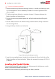
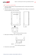

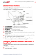


Table Of Contents
- Disclaimers
- Revision History
- HANDLING AND SAFETY INSTRUCTIONS
- Chapter 1: Overview
- Chapter 2: Installing and Connecting the Backup Interface
- Chapter 3: System Configuration
- Troubleshooting
- Appendix A: Manually Switching the System to the Grid-connected Mode
- Appendix B: Connecting External CTs
- Appendix C: System Performance LED Indication
- Appendix D: StorEdge Backup Interface Technical Specifications
- Support Contact Information

To connect to the Grid and Loads panels
1.
Release the six Allen screws of the Backup Interface cover and remove the cover.
NOTE
Do not remove the internal plastic cover (dead front).
2. Install a conduit of the required diameter into the Loads conduit entry. Use the
conduit holder to support the conduit.
3. Install a conduit of the required diameter into the Grid conduit entry. Use the
conduit holder to support the conduit.
4.
Remove the plastic covers from Loads terminals.
5. If required, connect the grounding and neutral bars with the bonding, supplied with
the Backup Interface. Tighten the bonding screws with a torque of 41 lb*in / 4.7
N*m.
6. Pass the cable from the AC Loads panel through the Loads conduit.
7.
Pass the cable from the grid through the Grid conduit.
8. Connect the neutral and grounding wires to the neutral and grounding terminals.
Tighten the terminal screws with a torque of 200 lb*in / 22.5 N*m.
9.
Connect Line 1 and Line 2 wires from the ACloads panel to the loads line terminal.
Tighten the terminal screws with a torque of 200 lb*in / 22.5 N*.
Figure 8: Connection to the ACLoads Panel
Backup Interface Installation Guide MAN-01-00728-1.0
14 Connecting the Backup Interface to the Grid and AC Loads Panel