
Install Manual
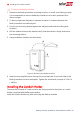
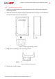
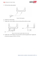
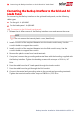
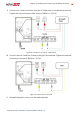
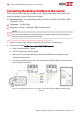
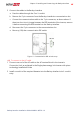
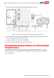
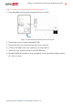
Table Of Contents
- Disclaimers
- Revision History
- HANDLING AND SAFETY INSTRUCTIONS
- Chapter 1: Overview
- Chapter 2: Installing and Connecting the Backup Interface
- Chapter 3: System Configuration
- Troubleshooting
- Appendix A: Manually Switching the System to the Grid-connected Mode
- Appendix B: Connecting External CTs
- Appendix C: System Performance LED Indication
- Appendix D: StorEdge Backup Interface Technical Specifications
- Support Contact Information

Connecting the Backup Interface to the Inverter
When connecting the Backup Interface to the Single phase energy hub inverter with
prism technology, use the following cable types:
Communication - 5-wire shielded twisted pair cable, 24 AWG (16-24 AWG), 600V
insulated or CAT5)
12V power - 16 AWG cable
ACpower - 6 AWG (4-20 AWG), 600V insulated cable
NOTE
If an auto-transformer is connected to the inverter, make sure to disconnect it
before connecting the Backup Interface.
To connect to the communication cable and 12V cable
1. Install a conduit of the required diameter into the Com 1 conduit entry.
2.
Connect the cabels to the Connection Unit of the inverter:
a. Open Communication 1 gland.
b. Pass the cables through the gland.
c. Remove the 7-pin connector from the slot labeled Backup Interface on the
communication board.
d.
Connect the cable wires to the 7-pin connector, as shown below, and reconnect
the connector to the slot:
Figure 10: Communication and 12V cables connection between Backup Interface and
Inverter
Backup Interface Installation Guide MAN-01-00729-1.0
16 Connecting the Backup Interface to the Inverter