
Install Manual
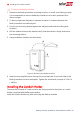
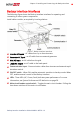
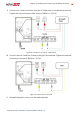
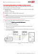
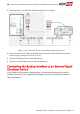
Table Of Contents
- Disclaimers
- Revision History
- HANDLING AND SAFETY INSTRUCTIONS
- Chapter 1: Overview
- Chapter 2: Installing and Connecting the Backup Interface
- Chapter 3: System Configuration
- Troubleshooting
- Appendix A: Manually Switching the System to the Grid-connected Mode
- Appendix B: Connecting External CTs
- Appendix C: System Performance LED Indication
- Appendix D: StorEdge Backup Interface Technical Specifications
- Support Contact Information

Backup Interface Interfaces
The following figure shows the Backup Interface interfaces for operating and
connecting to other system components.
Install cable conduits, as required by local regulations.
Figure 7: Backup Interface Interfaces
Inverter AC inputs - ACcables from up to three inverters.
Generator AC input - an ACcable from one external generator.
Grid ACinput - an ACcable from the grid.
Loads ACoutput - an ACcable to the loads panel.
Communication input - Communication cables from inverters and external rapid
shutdown switch.
ON/OFF switch - When ON, enables automatic transition to backup mode. When
OFF, enables manual control of the Backup Interface.
LEDs - Three LEDs (AC, Comm, Fault) indicate system performance. For more
information, see
System Performance LEDIndication
on page 26.
Maincircuit breaker control switch - Toggles the main circuit breaker. Pulling the
lever down switches off the main circuit breaker.
Chapter 2: Installing and Connecting the Backup Interface 13
Backup Interface Installation Guide MAN-01-00729-1.0