
Manual


Step 6 - Reset Switch: Stick it into the PCB, and solder it in!
Step 7 - 6-Pin Programming Header: Jam the 6-pin header into position
“Prg”. This is where you will plug in your USB / Serial converter.
Step 4 - 16MHz Resonator: This
gets installed in position ‘Xtl’. It
doesn’t matter which-way-
around it goes in.
Step 5 - LED: It’s an Arduino-
clone. It has to have a pin-13
LED installed onboard! Unlike
the resonator, make sure you
have the shorter lead in the
square pad (or just make
sure the LED matches the
outline on the PCB).
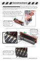
Construction!
Step 4: Install
16MHz Resonator
to position ‘Xtl’
Step 5: Install
LED to position
‘LED’ (watch
orientation!)
Step 6: Install
the Reset Switch
Step 7: Install the 6-pin programming
header in position ‘Prg’
Step 8:
Mount each
14-pin strip
from the
underside
of the PCB
Step 8 - 14-Pin Mounting Rails: Now
we are getting close to completion!
Mount the 14-pin headers on the
underside of the board.
www.solarbotics.com
5
Ardweeny Manual v1.3