
Documentation
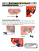
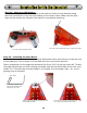
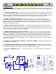

Step 15 - Mounting the Tail Spring Ring:
Lay your new ring over the tail spring so the spring is in the middle. You’re doing this so you
can see where to bend the wire 90° downward so that it goes into the pad just beside the tail
spring.
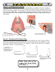
After you make the bend,
insert the wire into the hole
so the ring stands about 9mm
(3/8”) above the PCB, solder
it from the top, and clip it off
so there’s 6mm (1/4”) left
underneath (for adjusting).
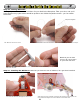
The wire will get hot while
soldering, so use some
masking tape to hold it at the
right height when you solder
it in.
15A: Lay ring over spring, and note
where you have to fold the wire down to
meet the solder pad
15B: Use masking tape
to hold the wire at the
9mm (3/8”) while you
solder it in.
9mm
(3/8”)
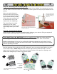
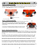
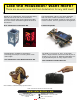
Step 16 - Preparing the Motors:
Slide the black rubber tires onto the white plastic hubs on your motors. Find your square of
double-sided sticky tape (DSST) and half and quarter it.
STOP! WAIT! Don’t do ANYTHING until you read this first: Wipe the motors and PCB
mounting spot with alcohol or window cleaner - it makes the DSST stick much better.
Put the motors down in front of you so the plus signs are nearest to each other. Put the
DSST on the flat part, up near the rear of the motor. Get this part wrong, and your Herbie
will love spinning in circles!
16A: Slide the rubber tire onto the
motor’s shaft
Pluses are
close!
Tape on
clean motor
surface!
16B: DSST stuck on the motors
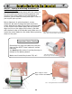
16C: Solder on wire clippings
13
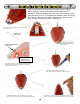
Peel the backing off one side of the DSST and push it onto one motor hard. Before you do it
on the other motor, make sure that with the plus signs side-by-side the DSST is on the
upper surface of both motors. Then take your saved resistor and capacitor clippings, and
solder them straight-up on each of the motor posts.
Solarbotics Herbie the Mousebot