
Documentation
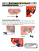
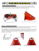

13A: Thread the Tail Spring
through the hole from this side
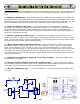
Step 13 - Installing the Tail Spring:
While we are working on the “rear end” of the Herbie, let’s add the tail. Your tail has a
solderable sleeve crimped on the end. Thread it through from the component side of the
PCB, and let it hang down. The best way to do this is put the Herbie on its back and lay it
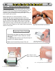
over the edge of the table, so the tail spring dangles downward. Solder the sleeve to the
pad, and you’re done! Don’t skimp on the solder. Make sure you’ve got a good, strong
connection.
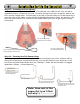
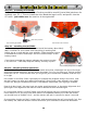
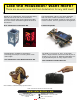
Step 14 - Forming the Tail Sensor Ring:
It’s one thing to have a tail spring, and another to actually turn it into a sensor. We’re
doing this by putting a ring around the tail, so if the tail is bent in any direction, it will
touch the ring and make Herbie kick into “Backup!” mode. We do this with a 3-legged
iguanodon, whups, I mean paperclip.
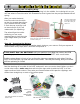
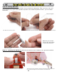
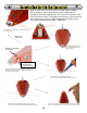
14A: Your run-of-the-mill
standard paperclip
14B: Pry it apart
14C: Turn one end into a loop
and snip the extra wire off
14D: Bend the loop so the wire
leg shoots directly out of it, and
cut off the rest.
Note: Save rest of the
paperclip! (you’ll find
out why...) (bet you hate it when we say that)
Cut
12
Solarbotics Herbie the Mousebot
13B: Let the tail dangle
underneath while soldering
13C: Use a good amount
of solder to mount the tail