
Documentation
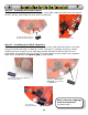
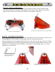
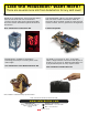

Step 11 - Installing the Power Switch:
Gotta be able to turn your Herbie off and on, right? Well, slide the switch into this slot as
far as it will go, and solder the pins down to the pads.
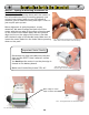
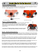
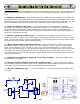
Step 12 - Installing the 0.22µF Capacitor:
This capacitor is part of the “Backup!” behavior circuit, and with the resistor, sets how
long your Herbie will stay in “Backup” mode. This part is “polarity-sensitive”, which
means you have to get it in the right way around, because it will not work if it’s in
backwards. See the side with the stripe? The lead closest to this stripe is the negative
lead, and is installed in the square pad at position C1.
11A: Slide the switch into the slot
and solder the leads to the pads
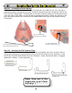
11B: Switch soldered in place
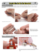
12A: With the strip face up, bend the
leads as shown above
12B: Install the capacitor into
position C1. Make sure the
short lead (-) is installed in
the square pad.
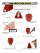
12C: Capacitor
installation Finished
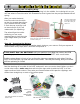
Note: Save the clippings
from the capacitor
(you’ll find out why...)
11
Solarbotics Herbie the Mousebot