
Documentation

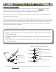


Step 1 - Preparing the Printed Circuit Board (PCB):
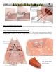
We start by snapping the three circuit boards apart. See those little tabs? They have to be removed
too. We find that pressing down at an angle against something hard (no, not your little brother’s
head) will make then pop off, or just use your snips to cut them off. Make sure you’re wearing your
eye protection!
See the little grooves left behind by the tabs? You have to use some sandpaper or a file to smooth
these down. Besides making your Herbie look better, it will actually make assembly easier.
1A. Snapping the PCBs apart & removing tabs by
pressure on the table or cutting with snips
1B. Filing down the tab grooves
1C. Tab Grooves
Bad!
1D. Tab Grooves
Gone!
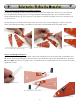
Step 2 - Soldering in the Eyes!:
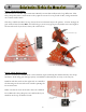
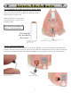
YES, we’re going to jump in with some component soldering. Now is the best time to install the two
IR sensors. Start by bending the leads down 90° away from the curved side. Install them to locations
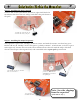
PD1 and PD2 (note there is a proper side - it’s labeled!). You want the flat side of the sensor to lay flat
against the board.
2B. Install IR Sensors at PD1 & PD2
2A. Fold the leads 90° towards
the flat side
2C. IR Sensor soldered in flat against PCB
3
Solarbotics Herbie the Mousebot