The ® Herbie the Mousebot Herbie the Mousebot is a very speedy lightseeking robot with functional whisker and tail sensors! Build multiple Herbies and have them chase each other around! ® Ltd.
Solarbotics Herbie the Mousebot Tools: Basic Soldering Equipment Eye protection (goggles) Needle-nose pliers Fine snips Medium/heavy duty snips Scissors / Knife Masking Tape Flashlight or IR Remote control (for testing) Parts: 1 - Herbie PCB (3 Pieces) 1 - Herbie Battery Board 1 - LM386 1 - 8-Pin IC Socket (for the LM386) 2 - Infrared Photodiodes 1 - 3904 Transistor 1 - Relay 1 - Power Switch 1 - Tail Spring Sensor 1 - 4.
Solarbotics Herbie the Mousebot Background: Many, many moons ago, Randy Sargent was in a pickle. Not literally (yuck), but more of an uncomfortable position of not having a robot to bring to the 1996 Seattle Robothon “Line Follower” contest. Would you believe the robot he cobbled up out of spare parts the night before the competition actually won?!? No, neither would we. It actually ended up in last place, but it still impressed the heck out of everybody with how simple and effective it was.
Solarbotics Herbie the Mousebot Soldering - The Essentials: The most important skill needed to successfully construct your device is soldering. Soldering is melting a special metal (called, um..., “solder”) between two components to make an electrical connection. We can also use solder like glue, to build things out of metals. You must make sure to use electrical solder, and not plumbers solder, which is used for piping and really isn’t good for electronics.
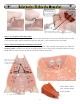
Solarbotics Herbie the Mousebot Step 1 - Preparing the Printed Circuit Board (PCB): We start by snapping the three circuit boards apart. See those little tabs? They have to be removed too. We find that pressing down at an angle against something hard (no, not your little brother’s head) will make then pop off, or just use your snips to cut them off. Make sure you’re wearing your eye protection! See the little grooves left behind by the tabs? You have to use some sandpaper or a file to smooth these down.
Solarbotics Herbie the Mousebot Step 3 - Preparing the Main Solder Pads: We’re going to pre-tin 8 pads on the PCBs so all we have to do is align them and reheat to make them stick. Make sure you melt a generous amount of solder on these pads, like shown in figure 3B.
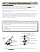
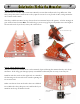
Solarbotics Herbie the Mousebot Whaa?!? See? The half-circles here are OUT OF ALIGNMENT! (yes, we had to fix this assembly error) 4B: GAAAH! Misaligned! Battery clips face rearward! Remelt solder to join boards 4C: See? Align edge-to-edge! 4D: Remelt the Solder to join the sides. Note how the battery connector is facing backwards. Step 5 - Do it again for the other side!: No pictures here - just repeat the process for the other side board.
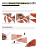
Solarbotics Herbie the Mousebot Step 7 - The Backup Relay: This was one of our little improvements to Randy’s circuit that really made a big difference. This relay swaps the motor connections so they spin in reverse for a set period of time, and gets Herbie out of most traffic snarls. The relay could be mounted on top, but we don’t recommend it (see the picture - it looks strange). It gets soldered into location RE1, and will only go in one way (goof-proof!). Make it nice and tight to the circuit board.
Solarbotics Herbie the Mousebot Step 9 -Installing the 4.7k Resistor (Yellow / Purple / Red): The 4.7k resistor is part of the “Backup!” behavior circuit. It doesn’t care which way it’s installed. It’s marked with the stripes Yellow / Purple / Red. Bend the leads 90° down close to the resistor body, so it goes into the holes easily. TIP: SAVE THE CLIPPINGS! (trust us - you’ll need them) Don’t mix this one up with the R2 resistor! 9A: Bend the 4.
Solarbotics Herbie the Mousebot Step 11 - Installing the Power Switch: Gotta be able to turn your Herbie off and on, right? Well, slide the switch into this slot as far as it will go, and solder the pins down to the pads. 11A: Slide the switch into the slot and solder the leads to the pads 11B: Switch soldered in place Step 12 - Installing the 0.22µF Capacitor: This capacitor is part of the “Backup!” behavior circuit, and with the resistor, sets how long your Herbie will stay in “Backup” mode.
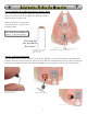
Solarbotics Herbie the Mousebot Step 13 - Installing the Tail Spring: While we are working on the “rear end” of the Herbie, let’s add the tail. Your tail has a solderable sleeve crimped on the end. Thread it through from the component side of the PCB, and let it hang down. The best way to do this is put the Herbie on its back and lay it over the edge of the table, so the tail spring dangles downward. Solder the sleeve to the pad, and you’re done! Don’t skimp on the solder.
Solarbotics Herbie the Mousebot Step 15 - Mounting the Tail Spring Ring: Lay your new ring over the tail spring so the spring is in the middle. You’re doing this so you can see where to bend the wire 90° downward so that it goes into the pad just beside the tail spring. After you make the bend, insert the wire into the hole so the ring stands about 9mm (3/8”) above the PCB, solder it in, and clip it off so there’s 6mm (1/4”) left underneath (for adjusting).
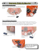
Solarbotics Herbie the Mousebot Step 17 - Mounting the Motors to the Herbie Body: Motor alignment is quite important, so pay attention! We want to align the black top of the motor with the top edge of the silver mounting pad on the inside of the Herbie body. We also want to align the line on the edge of the motor’s flat side with the back edge of the Herbie body.
Solarbotics Herbie the Mousebot Step 18 - Wiring up the Motors: Now it’s time to solder the motor leads to the pads on Herbie’s body. Besides being electrical connections, they also help stiffen up the motor mount. Make sure the white spots on the motors are closest to the Herbie’s nose before soldering! 17E: Side view of Herbie with motors. Looks good, right? 17D: Rear view of installed motors Step 19 - Installing the Nose Bead: We’re using a very hard hematite bead for the nosewheel.
Solarbotics Herbie the Mousebot Step 19 - Installing the LM386: No slow 286 chip for us, and a 486 or Pentium would be overkill (just a little joke there for anybody over 30...). Time to install the chip! Just make sure the notch is on the right side when you push it into the IC carrier, and all will be fine. 19A: Installing the LM386 Note notch position! 19B: Herbie brains installed Step 20 - Installing the BATTERY!: Yes, we’re going to take a BOLD step and install the battery. Now.
Solarbotics Herbie the Mousebot Step 22 - Making Whiskers!: We’re going to make two sets of whiskers for your Herbie the Mousebot. Take your time, and you’ll have whiskers any cyber-rodent would be proud to own. Make the bends smooth - you can tweak them later.
Solarbotics Herbie the Mousebot Look in your kit for a short piece of heat shrink tubing. We’re going to use it as a spacer while soldering the whiskers. Slide the tubing over the end of the sensors, and into the sensor hole. This keeps the whiskers from touching the sensor hole, which is only supposed to happen when they hit something and make it “Backup!” 23C: Slide the spacer tube over the sensors into the sensor hole.
Solarbotics Herbie the Mousebot Troubleshooting! The Solarbotics Herbie the Mousebot is a pretty straightforward device, so let’s step through the list and hopefully we’ll find your problem. If not, give us a call, and we’ll be happy to work with you to fix it. 1. “Nothing is happening!” - Even without the chip, Herbie should do something, so there must be a problem with power. Make sure you have the soldered the power tabs on the battery board to the main board.
Solarbotics Herbie the Mousebot Herbie Enhancement: The Herbie the Mousebot Tail-Light!: We thought that it would be fun to add “play with me” functionality to the Solarbotics Herbie the Mousebot. What we did is add a location for an Infrared Light Emitting Diode, which is like a regular LED, but shines IR light, which Herbie’s eyes are tuned for. By shining this light from Herbie’s rear, it shows other Herbies where it is (”Come and get me! Nyah, nyah...”).
Like the Mousebot? Want more? There are several more kits from Solarbotics for any skill level! The SolarSpeeder 2 Kit is a very quick Solaroller that can cover 3 meters (10 feet) in under 40 seconds in direct sunlight. Simple to construct and a blast to watch, this is a great kit for all beginners! K HP-L HexPummer Lantern $33.50USD/CAD K SS Solarspeeder . . . . . . . . $27.50USD/CAD NEW! Based on our HexPummer, this kit charges all day from the SCC3733 solar cell.