
SA-12K Install Guide and Owner Manual
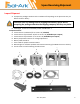
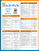
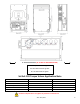
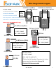
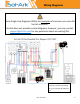
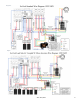
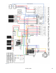
Table Of Contents
- Spec Sheet
- Wiring Diagrams
- GUI Screens
- Physical Installation
- Inverter Components
- Deciding Backup Circuits
- Single System Installs
- Mounting the Sol-Ark
- Integrating Batteries (Sol-Ark POWERED "OFF")
- E.M.P Systems Only
- Connecting Solar Panels
- Integrating a Generator
- Integrating Sensors and Accessory Placement
- Battery Temperature Sensor
- Limiter Sensors (CT Sensors)
- GEN Start Signal (Two-Wire)
- CANbus & RS485
- Wi-Fi Antenna (Dongle)
- Emergency Stop Signal & PV Rapid Shutdown Signal
- Misc. Hardware Recommendations
- Check the voltage on each PV input circuit
- Check Grid Input Voltage
- Check Battery Voltage
- Provide Power to Sol-Ark
- Indicator LED's
- Power Cycle Sequence
- Wi-Fi / Internet Connection
- Programming Guide
- Limiter Sensors (CT Sensors)
- Install Tips
- Batteries
- Parallel Systems
- Troubleshooting Guide
- LCD is not powering on
- Panels are connected, but DC Light is not on
- Panels are not producing
- Panels are not producing much power
- The system does not keep batteries charged
- Auto Gen-Start not working
- Normal LED isn't on
- The alarm light is on
- Grid HM value is negative when it should be positive (only applies in limited home mode)
- AC Overload Fault or Bus Unbalance Fault
- The system connects to grid and quickly disconnects
- DC Overload Fault
- System is beeping
- Battery cable sparks when connected
- Battery symbol on the home screen is red
- Battery symbol on the home screen is yellow
- Grid symbol on the home screen is yellow
- System has restarted
- Batteries were connected backward
- Why is the LCD screen still on when the power button is off?
- The Batt % meter is not reaching 100%
- Generator setup is reading 0Hz
- Color Touchscreen is Frozen
- Consant F18 Faults while powering loads within specification
- Troubleshooting Phasing Issues
- Sol-Ark 12K Error Codes
- Install Verification Checklist
- Sol-Ark 12K Limited Warranty

June 30
th
, 2022 7
Wire Gauge Guide (copper)
PV input: 10AWG
All AC Inputs/Outputs: 6-4AWG
All Sensors: 20-24AWG
CT Sensors: 10' Wire Included
Batt Temp Sensor: 6' Wire Included
RJ45 Cable: 7' Included (Extendable up to 20')
Battery input: 2/0-4/0AWG (3/8
"
Lugs)
All Sensor Inputs
0’ – 100’: 24 AWG
100’ – 400’: 23 AWG CAT 6
CT Wires Can Be Extended -Extensions for Limiter
Sensors must be twisted pair (See pg. 39)
(Shielded CAT6 Recommended)
DC Battery Input
0’ – 12’: 2/0 AWG
12’ – 20’: 4/0 AWG
All AC Inputs / Outputs /
Neutral Connections
0’ – 100’: 6 AWG
2/0 AWG Max
4/0 AWG Max
Small
Limiter
Sensor
Large
Limiter
Sensor
15.875mm (5/8in)
10 AWG Max
PV Panel Inputs
0’ – 100’: 12 AWG
100’ – 300’: 10 AWG
25.4mm (1.0in)
10mm
4/0 AWG Max
15.875mm (5/8in)
4 AWG Max
200A: 0.1A
+
-
23.813mm (15/16in)
100A: 50mA
15.875mm (5/8in)
+
-
6.35mm
(1/4in)
20 AWG Max