
SA-12K Install Guide and Owner Manual
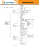
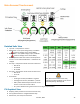
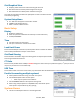
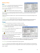
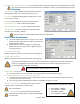
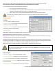
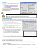
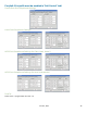
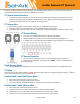
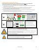
Table Of Contents
- Spec Sheet
- Wiring Diagrams
- GUI Screens
- Physical Installation
- Inverter Components
- Deciding Backup Circuits
- Single System Installs
- Mounting the Sol-Ark
- Integrating Batteries (Sol-Ark POWERED "OFF")
- E.M.P Systems Only
- Connecting Solar Panels
- Integrating a Generator
- Integrating Sensors and Accessory Placement
- Battery Temperature Sensor
- Limiter Sensors (CT Sensors)
- GEN Start Signal (Two-Wire)
- CANbus & RS485
- Wi-Fi Antenna (Dongle)
- Emergency Stop Signal & PV Rapid Shutdown Signal
- Misc. Hardware Recommendations
- Check the voltage on each PV input circuit
- Check Grid Input Voltage
- Check Battery Voltage
- Provide Power to Sol-Ark
- Indicator LED's
- Power Cycle Sequence
- Wi-Fi / Internet Connection
- Programming Guide
- Limiter Sensors (CT Sensors)
- Install Tips
- Batteries
- Parallel Systems
- Troubleshooting Guide
- LCD is not powering on
- Panels are connected, but DC Light is not on
- Panels are not producing
- Panels are not producing much power
- The system does not keep batteries charged
- Auto Gen-Start not working
- Normal LED isn't on
- The alarm light is on
- Grid HM value is negative when it should be positive (only applies in limited home mode)
- AC Overload Fault or Bus Unbalance Fault
- The system connects to grid and quickly disconnects
- DC Overload Fault
- System is beeping
- Battery cable sparks when connected
- Battery symbol on the home screen is red
- Battery symbol on the home screen is yellow
- Grid symbol on the home screen is yellow
- System has restarted
- Batteries were connected backward
- Why is the LCD screen still on when the power button is off?
- The Batt % meter is not reaching 100%
- Generator setup is reading 0Hz
- Color Touchscreen is Frozen
- Consant F18 Faults while powering loads within specification
- Troubleshooting Phasing Issues
- Sol-Ark 12K Error Codes
- Install Verification Checklist
- Sol-Ark 12K Limited Warranty

June 30
th
, 2022 33
Grid Graphical View
A. Displays power drawn from and sold to the grid over time
B. Bars above the line indicate power bought from the grid
C. Bars below the line indicate power sold back to the grid
This view can help determine when the peak power is used in the Home and for
Time of Use programing
System Setup Menu
A. ID = LCD serial #. Support uses the Wi-Fi serial #.
B. COMM = LCD software version
C. MCU = Inverter software version
Basic Setup
Display
A. Brightness adjustment
B. Auto dim (must be enabled for the warranty to cover LCD screen)
C. Enable/disable BEEP
Time
A. Set date and time for the system
B. Set up to 3 seasons for Time of Use to follow
Load Limit Power
Set the total AC Output of the Sol-Ark, excess power will be curtailed. The default
value is always the Maximum output of the inverter.
Grid Peak Shaving
Set the Sol-Ark's threshold to begin contributing power to keep the power drawn
from the grid below the threshold.
CT Ratio
Set the CT ratio; Default value is 2000/1. DO NOT change this value unless you speak with support, 3
rd
party CT sensors
require our permission to not void warranty.
UPS Time
Set the UPS transfer time to the chosen value; any value below 4ms will default back to a 4ms transfer time.
Parallel (connecting multiple systems)
A. Select parallel mode when using more than one system
B. Set the Master/Slave status of each system
i. Label only one system as the "Master"
C. Set the MODBUS address of each system starting at 01
D. When using multiple Systems in 120/208V mode, select which phase
each system is responsible for (A, B, C) (see pg.
System Alarms
A. Lists all recorded System alarms in chronological order