
SA-12K Install Guide and Owner Manual
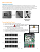
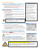
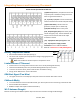
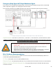
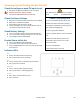
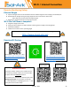
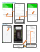
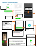
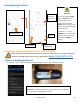
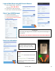
Table Of Contents
- Spec Sheet
- Wiring Diagrams
- GUI Screens
- Physical Installation
- Inverter Components
- Deciding Backup Circuits
- Single System Installs
- Mounting the Sol-Ark
- Integrating Batteries (Sol-Ark POWERED "OFF")
- E.M.P Systems Only
- Connecting Solar Panels
- Integrating a Generator
- Integrating Sensors and Accessory Placement
- Battery Temperature Sensor
- Limiter Sensors (CT Sensors)
- GEN Start Signal (Two-Wire)
- CANbus & RS485
- Wi-Fi Antenna (Dongle)
- Emergency Stop Signal & PV Rapid Shutdown Signal
- Misc. Hardware Recommendations
- Check the voltage on each PV input circuit
- Check Grid Input Voltage
- Check Battery Voltage
- Provide Power to Sol-Ark
- Indicator LED's
- Power Cycle Sequence
- Wi-Fi / Internet Connection
- Programming Guide
- Limiter Sensors (CT Sensors)
- Install Tips
- Batteries
- Parallel Systems
- Troubleshooting Guide
- LCD is not powering on
- Panels are connected, but DC Light is not on
- Panels are not producing
- Panels are not producing much power
- The system does not keep batteries charged
- Auto Gen-Start not working
- Normal LED isn't on
- The alarm light is on
- Grid HM value is negative when it should be positive (only applies in limited home mode)
- AC Overload Fault or Bus Unbalance Fault
- The system connects to grid and quickly disconnects
- DC Overload Fault
- System is beeping
- Battery cable sparks when connected
- Battery symbol on the home screen is red
- Battery symbol on the home screen is yellow
- Grid symbol on the home screen is yellow
- System has restarted
- Batteries were connected backward
- Why is the LCD screen still on when the power button is off?
- The Batt % meter is not reaching 100%
- Generator setup is reading 0Hz
- Color Touchscreen is Frozen
- Consant F18 Faults while powering loads within specification
- Troubleshooting Phasing Issues
- Sol-Ark 12K Error Codes
- Install Verification Checklist
- Sol-Ark 12K Limited Warranty

June 30
th
, 2022 24
Emergency Stop Signal & PV Rapid Shutdown Signal
Pins 11 and 12 use a normally open & latching switch to connect the two emergency stop pins that cut off the RSD
power supply when triggered, thus stopping the inverter AC output.
Pins 15 and 16 provide the 12V / 100mA signal power lost when the Sol-Ark shuts down using the front button.
Emergency Stop Diagram (Only available on select hardware versions | Shown with TIGO TS4)
Rapid Shutdown: TIGO TS4-A-O | TIGO TS4-A-F | TIGO TS4-O | TIGO TS4-O-DUO | APsmart RSD S-PLC / RSD-D
PARALLEL SYSTEMS: Emergency Stop should be connected to the Master with address 01 and will initiate emergency
stop for all paralleled systems from the one button
Misc. Hardware Recommendations
Disconnect / Transfer Switches: 200A Non-Fused Transfer Switch Model #TC10324R (GE) | 200A Fused
Transfer Switch Model #DG224NRK (Eaton)
PV Fuses: 15A PV MC4 in-line fuse holder (ZOOKOTO or DPJ)
Electrical Panel: Any appropriately rated panel for your loads (Check local hardware stores for recommendations)
Battery Combiners (Parallel Systems Only): Any appropriately rated pair of Bus Bars with 3/8” battery
connection terminals
• The Built-in 12V power supply in the user area of the Sol-Ark (Pins 15 and 16) is rated for
100mA (1.2W)
• Transmitter fits inside the user area of the Sol-Ark 12K but can cause interference
(sometimes requires placing it outside of the user area)
• TIGO Optimizers are compatible with the Sol-Ark 12K (Do not use the built in 12V Power
supply in the Sol-Ark user area to Power the Tigo Optimizer TX transmitter)