
SA-12K Install Guide and Owner Manual
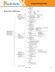
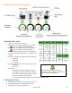
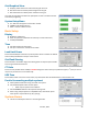

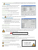
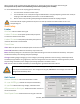
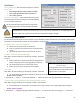
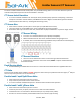
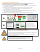
Table Of Contents
- Spec Sheet
- Wiring Diagrams
- GUI Screens
- Physical Installation
- Inverter Components
- Deciding Backup Circuits
- Single System Installs
- Mounting the Sol-Ark
- Integrating Batteries (Sol-Ark POWERED "OFF")
- E.M.P Systems Only
- Connecting Solar Panels
- Integrating a Generator
- Integrating Sensors and Accessory Placement
- Battery Temperature Sensor
- Limiter Sensors (CT Sensors)
- GEN Start Signal (Two-Wire)
- CANbus & RS485
- Wi-Fi Antenna (Dongle)
- Emergency Stop Signal & PV Rapid Shutdown Signal
- Misc. Hardware Recommendations
- Check the voltage on each PV input circuit
- Check Grid Input Voltage
- Check Battery Voltage
- Provide Power to Sol-Ark
- Indicator LED's
- Power Cycle Sequence
- Wi-Fi / Internet Connection
- Programming Guide
- Limiter Sensors (CT Sensors)
- Install Tips
- Batteries
- Parallel Systems
- Troubleshooting Guide
- LCD is not powering on
- Panels are connected, but DC Light is not on
- Panels are not producing
- Panels are not producing much power
- The system does not keep batteries charged
- Auto Gen-Start not working
- Normal LED isn't on
- The alarm light is on
- Grid HM value is negative when it should be positive (only applies in limited home mode)
- AC Overload Fault or Bus Unbalance Fault
- The system connects to grid and quickly disconnects
- DC Overload Fault
- System is beeping
- Battery cable sparks when connected
- Battery symbol on the home screen is red
- Battery symbol on the home screen is yellow
- Grid symbol on the home screen is yellow
- System has restarted
- Batteries were connected backward
- Why is the LCD screen still on when the power button is off?
- The Batt % meter is not reaching 100%
- Generator setup is reading 0Hz
- Color Touchscreen is Frozen
- Consant F18 Faults while powering loads within specification
- Troubleshooting Phasing Issues
- Sol-Ark 12K Error Codes
- Install Verification Checklist
- Sol-Ark 12K Limited Warranty

June 30
th
, 2022 39
Limiter Sensors (CT Sensors)
CT Sensors enable Limited to Home mode (meter zero) and Peak Shaving mode. CT sensors also allow the system to
calculate loads powered upstream of the Grid Breaker in the home.
CT Sensor Install Location
• CT sensors should be installed on L1 and L2 (also L3 for parallel 3 phase) upstream of everything in the home
except for a Generator Transfer Switch, Knife Blade Disconnect or Bypass Transfer Switch (upstream of Main
Service Panel and Line-Side Tap – see Diagrams Section Pgs. 8-16).
CT Sensor Size
• Each inverter includes a pair of 5/8” CT sensors (fits up to 2/0 AWG service wires).
• There are 15/16” (up to 4/0 AWG) and 2” sensors available for purchase if needed.
• Dimensions refer only to CT sensor hole size, contact Sales at (972) 575-8875 Ext 1 to purchase larger sensors.
CT Sensor Wiring
• CT sensor on L1 should be wired to pins 3 (white) and 4 (black).
• CT sensor on L2 should be wired to pins 5 (white) and 6 (black).
• White and black wires for each sensor should be twisted along length of run.
• If needed, wires can be extended using Shielded Cat 6 (use both wires of twisted pair).
CT Sensor Direction
• There is an arrow embossed on the CT sensor housing to determine direction.
• Install pointing upstream to the service meter, EXCEPT in 3 phase installs where this
should be reversed.
Peak Shaving Mode
• Grid Peak Shaving is available with the CT sensors in the location described above and applicable direction.
CT Ratio
Set the CT ratio; Default value is 2000/1. DO NOT change this value unless you speak with technical support, 3
rd
Party CT
sensors require our permission to not void warranty.
Parallel 120V/240V Split Phase Note
• Each inverter will come with a pair of CT sensors.
• Only install one pair and wire to the master inverter.
• CT sensors should be installed with system in Limited to Home mode for best operation.
Parallel 120V/208V 3 Phase Note
• Each inverter will come with a pair of CT sensors.
• Install only one sensor per phase, wire sensor for L1 and L2 to Phase A Master.
• Install third sensor on L3 and wire to Phase B master pins 5 (+ white) and 6 (- Black).
• Arrow on CT sensors should be pointed downstream to the inverters (3 phase only).
CT Sensor Extension Example