Smart Piezo Drive Programmable & Autoinstrumented 200 Volt amplifier User’s Manual by In association with July 2012 1040, avenue Belvédère, suite 215 Québec (Québec) G1S 3G3 Canada Tél.
1 WARNINGS _________________________________________________ 4 2 MAIN FEATURES ____________________________________________ 4 3 TECHNICAL DATA ___________________________________________ 4 4 SOFTWARE INSTALLATION ___________________________________ 6 4.1 Control Application (USB version) ________________________________________________ 6 4.
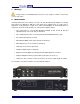
1 Warnings Voltages at the X, Y and Z BNC output connectors can go as high as +-200 VDC. This presents a risk of electrocution. 2 Main Features The Smart Piezo Drive is a 6-channels, very low noise and drift, high-voltage amplifier for ScanningProbe Microscopy applications. With three main inputs, three auxiliary inputs an a wide range of adjustments for the parameters (output offsets, gains and bandwidths), the Smart Piezo Drive is a feature-rich, extremely versatile product.
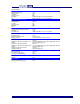
Technical Data Analog Input Channels (scanning) Main Inputs (X,Y and Z) Input Impedance Coupling Input Connectors Bandwidth Gain Analog Input Channels (auxiliary) Auxiliary Inputs (X,Y and Z) Input Resistance Coupling Input Connectors Bandwidth Gain Offset (software controlled) Software Adjustable Offset (X,Y and Z) Bandwidth Slew Rate Limit High Voltage Outputs Output Channels (X+,X-,Y+,Y-,Z+ and Z-) Maximum Current Maximum Capacitive Load Output Connectors Signal Quality Output Noise (gain x1 and 50kHz) O
3 Software Installation To install the high voltage amplifier software, launch the installer SoftdB_Smart_Piezo_Drive_V130.exe and follow the on-screen instructions. At the end of the installation procedure, the SR3Pro USB driver is automatically installed if it was not already. The highvoltage amplifier software is located in the following folder: C:\Program Files (x86)\SoftdB_ SoftdB_Smart_Piezo_Drive\ There are two versions of the amplifier control software: 1) USB version: Smart_Piezo_Drive.
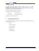
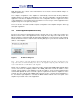
Figure 1 Control application (USB version) Use this button to change the sensitivity and the unit name for each channel. The output positions are presented in the user define units. All values displayed or entered can be appended with a 1-letter suffix that indicates the scaling factor: • m for mili • u for micro • n for nano • p for pico • f for femto Note: The absence of suffix implies that the scaling factor is 1.
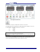
Figure 2 Output History Use the Output History Length control to change the amount of recorded history. The history can be reset using the Reset Histo button. The Offset Slew-Rate Limiter control specifies the maximum rate of change of the offset in V/s, and the value is the same for all the axes. The red emergency button can be used to return all offsets to a preset value.
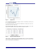
Figure 4 Drift correction dialog box Each drift correction value is scaled by the Sensitivity value that is set for the corresponding channel. With the USB version of the interface, a oscilloscope function can be used to monitor the output signals in real time. The sampling frequency is 75 kHz and the memory length is 60 s.
With this button, the controls of the main interface are locked to avoid accidental changes of amplifier parameters. The complete configuration of the amplifier is automatically saved in flash memory within the amplifier whenever a change in configuration occurs. The last configuration saved in flash will be applied the next time the amplifier is turned-on. The configuration in flash is applied even if the control application is not running.
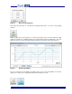
Figure 7 Control application (Ethernet version) Smart Piezo Drive - User’s Manual 11