Opus Suite Building Vib Module User Guide – V1.1b November 29, 2011 Compatible Hardware: Alto 6‐Channel Concerto 4‐Channel I‐Track 6‐Channel Soft dB Inc. 1040, Belvedere Avenue, Suite 215 Quebec (Quebec) Canada G1S 3G3 Toll free: 1‐866‐686‐0993 (USA and Canada) E‐mail: contact@softdb.
CONTENTS 1 Introduction ..............................................................................................................................1 2 Compatible Hardware................................................................................................................3 3 Opus Environment.....................................................................................................................4 4 Main Interface ................................................................
1 Introduction Congratulations on your purchase of the Opus Suite Building Vib Module. The Opus Software Suite is a Sound and Vibration software with six measurement modules: SLM 4ch module : 4 channels, Class 1 conform to IEC 60651, IEC 60804, IEC 61672‐1 SLM & 3Vib module : 1 SLM channel (same as SLM 4ch module) and 3 vibration channels conform to ISO 2631‐1 Data Logger module RT‐60 module Building Vib module Intensity module The Opus Suite is intended to run on a Concerto.
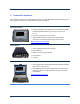
2 Compatible Hardware Every hardware option has an embedded state of the art Soft dB SR‐MK3 DSP board allowing real‐ time and precise measurement with very low energy consumption. Concerto 4‐Channel Handy, lightweight, fully rugged military grade (MIL‐STD‐810F and IP67) tablet PC with anti‐glare & anti‐scratch touch screen All in one instrument (no PC required) WLAN and Bluetooth communication allows using the Concerto as a monitoring station with remote access. www.softdb.com/concerto.
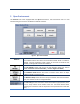
3 Opus Environment The Concerto unit comes equipped with the Opus Environment. This environment acts as a main interface that gives access to the different modules and tools. Figure 1 : Opus Suite Interface Modules The modules buttons will launch the associated module. When a module is opened, a license verification check is done. If no license is found for that module, a message will indicate the limitations.
The Clock indicator displays the time and date on the unit. To change time, simply click on the indicator to display a dialog window. The Quit button will quit the application differently according to the hardware used. Concerto hardware: ‐ Hold 5 sec to shutdown the unit. ‐ Press and release to enter standby mode. Alto‐6ch or I‐Track hardware: ‐ Press and release to close the application and return to Windows. Opus Building Vib User Guide – V1.
4 Main Interface The main interface is divided into five sections: 1) 2) 3) 4) 5) 6) 7) Measure controls (see section 6.1, p. 11) File info (see section 6.2, p. 11) Measure info (see section 0, p. 11) Menu bar (see section 6.3, p. 12) Waveforms (see section6.4, p. 13) Events peak spectrum (see section6.5, p. 14) Events table (see section 6.6, p.
5 Quick Start The Opus Building Vib Module monitors the vibration time signal from a triaxial accelerometer. When a specified vibration threshold is measured, an event record is triggered. Then, the event record is analysed to identify the peak for each axis and associated parameters. Each event record contains the simultaneous acceleration, velocity and displacement waveforms for each axis and the acoustic waveforms (Time Signal and Sound Pressure Levels (SPL)).
Step 5 Save the Measurement Click on the button to save the measurement. The measurement file will be saved as a .snv file in the file save directory. Its name will appear as a four digit number displayed in the File info section of the main interface. Step 6 Visualize the Measurement To visualize each event individually, click on the event table to select the desired event to display. When doing so, the event waveforms will be displayed on the waveform graphs at the left of the interface.
6 Main interface controls and indicators 6.1 Measure Controls RUN When the user clicks this button, the measurement process is launched. STOP/SAVE When the user clicks this button, the measurement stops. The STOP button then becomes the SAVE button. When the user clicks this button, the active measurement is saved. The SAVE button is then disabled until another measurement is complete. 6.2 File Info File Save This indicator displays the current measurement file.
Measure Info This indicator displays the start time of the current measurement file. This indicator displays the trigger setting of the current measurement file. The trigger value and the monitored axis are displayed. The signal type (acceleration, velocity or displacement) monitored by the trigger is implied in the trigger units. This indicator displays the event record length used for the current file. It displays both the record time before and after the trigger occurrence. 6.
6.4 Waveforms When a measurement is running these waveforms can display either the live signal or the selected event in the event table. This display mode is selected using the the main interface. button at the right side of This indicator displays either the Acoustic Channel Time Signal (RTA) or the SPL levels. Vibration X Axis Vibration Y Axis These indicators display the vibration time signal. Vibration Z Axis To change the displayed event, click on the Event table on the desired event.
6.5 Events Peak Spectrum This indicator displays each event X, Y and Z axis peaks and associated frequency. The frequency can be either FFT (DIN 4150) or Zero Crossing. A reference curve can be displayed on this spectrum. This reference curve can be DIN 4150 or USBM RI 8507. Use the Display Setup to change the settings of this indicator. 6.6 Events Table This indicator displays relevant information about each event.
7 Input Setup Click on the button to go to the Input Setup interface. This interface allows the user to: Select the input channel, Select the input type (default is ICP for standard accelerometers and microphones), Manually modify the microphone sensitivity or automatically using the microphone calibration function, Manually modify the accelerometer sensitivity or automatically using the accelerometer calibration function. Opus Building Vib User Guide – V1.
7.1 Step 1 Microphone Calibration Adjust the calibration parameters The defaults values are: Averaging time: Frequency: Calibrator Level: 5s 1 kHz 94 dB Step 2 Install the calibrator device on the microphone Step 3 Click START After the average time is elapsed, the sensitivity value will update.
7.2 Step 1 Accelerometer Calibration Adjust the calibration parameters The defaults values are: Averaging time: Frequency: Calibrator Level: 5s 159,2 Hz 1G Step 2 Fasten the accelerometer on the calibrator Step 3 Click START After the average time is elapsed, the sensitivity value will update. Step 4 Click OK to accept the sensitivity value Opus Building Vib User Guide – V1.
8 Display Setup Click on the button to go to the Input Setup interface.
9 Record Setup Click on the button to go to the Record Setup interface. The events are recorded when a specified trigger value is encountered on one or a combination of axis on the accelerometer. The trigger signal type, trigger value and units and the axis to monitor are set using the controls at the top of the interface. Two record times are to be set. The first one is the record length before trigger and the second one is the record time after trigger.
10 File Manager The File manager is used to perform most file operations: Navigate the directory structure Create folders Rename files and folders Move or copy files and folders from one place to another Delete a file or a folder Although not very useful on a stand alone computer, this manager is necessary on the Concerto, on which Windows explorer is unavailable.
Directory Path Displays the path of the active directory. Allows easy access to common directories. When the File Manager is used on a stand alone computer, these shortcuts are linked to: Desktop Shortcuts My Documents Computer When the File Manager is used on a Concerto, the shortcuts are linked to: Opus Root USB Device. Move/Copy Operators Copies or moves a file or folder from a source to its destination.
Appendix 1 : Concerto Hardware Connections Mic Stand Camera Loudspeaker 4 Inputs DC in Headphone Jack Power‐on button 2 Outputs ¼ 20 insert Second Battery USB port Microphone Battery indicator Right click Opus Building Vib User Guide – V1.
Power on/off Power‐on Turn On Turn Off Press the trigger button located at the back of the unit This key has two (2) functions: a) To turn the unit ON. b) Start a measurement once the SLM Module is loaded After a few seconds, the Opus Environment Interface will appear. The stand‐by mode allows fast load time. Stand‐by Shutdown 26 To put the unit on stand‐by, click the Turn Off button.
Power Reset If the Concerto happens to crash and it is not possible to take back the control, a power reset might be necessary. To complete the power reset, the three buttons on the front of the Concerto must be used.
Concerto Hardware Specifications DSP board: Signal‐RangerTM SR3 by Soft dB Processor TI TMS320C6424, 96 kHz/24‐bit Real time bandwidth DC to 24 kHz @ 4 channels Dynamic Range 94 dB per range (105 dB total) Noise floor (@ 50mV/Pa) 25 dBA 30 dBC 30 dBZ THD + noise > 90 dB@ 1/4 dynamic range Cross talk > 115 dB @ 1kHz Random noise < 14 μV(A), < 17 μV(Z) @ 0.1 Hz Decimation rates 2, 4, 8, 10 (for .
PC Platform Tablet PC (Model M8910 From DAP Technologies inc). Operating system AMD® Geode™ LX800 Processor, 500MHz 512MB DDRAM System Memory 4GB high‐speed solid state drive; up to 20GB Microsoft Windows XP Embedded Display WVGA 7.0” 800 x 480 transmissive color TFT LCD, 450 nits Anti‐glare, scratch and shock resistant touch screen treatment Connectivity USB; (WLAN, Bluetooth options available). Battery operation 1 Primary internal battery, 2600 mAh, 7.