When connecting to the Admin, Advanced User or Cyber security profiles for the first time, it is mandatory to change default passwords. If these passwords are not changed, the "Password alert" alarm will remain active. It is highly recommended to change all default passwords right away, especially the password of the Cyber security profile which has the highest privileges including changing passwords for other accounts.
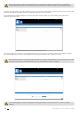
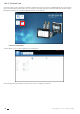
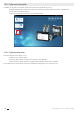
10.2. Admin profile When connected as Admin, you can access the configuration page by clicking on the “wrench/screwdriver” icon on the top left corner: 10.2.1.
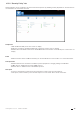
• Click on “Modify active configuration” (1), and then click on “Sources” (2): 2 1 • Click on the “AutoDetect” icon on the right bottom corner to detect and add SOCOMEC devices already present in the D-50/D-70 display’s topology. • Click on the “+” icon at the right bottom corner for manually adding products one at a time. Adding an M-50/M-70 gateway or D-50/D-70 display will add the entire topology under that gateway or display.
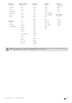
Gateways DIRIS Digiware COUNTIS DIRIS A Switches D-50 D-40 Ci A-10 ATyS p M D-50v2 I-30 E03 A-20 C55 D-70 I-30 dc E04 A-30 C65 G-30/G-40 I-31 E13 A-40 C66 G-50/G-60 I-33 E14 A-40 Ethernet M-50 I-35 E17 A-40 Profibus M-70 I-35 dc E18 A14 A10 I-43 E23 A17 A20 DIRIS B I-45 E24 A17 2In A20v2 B-10 I-60 E27 A17 THD A40v2 B-30 RF I-61 IO-10 E28 A17 THD In A40v3 E33 A60 E34 A80 B-30 RS485 IO-20 S-130 S-135 S-Datacenter U-10 U-20 U-30 U-31 dc U-32 dc Old
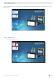
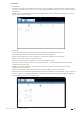
10.2.2. “Protocols” tab Once the system is fully configured to visualise measurements and consumption on WEBVIEW-M, the communication protocols which will be used by the D-50/D-70 display to exchange data with an external supervisor (SCADA, Energy Management System, etc.) can be configured from the “Protocols” tab. • Network Configuration This tab allows you to modify the gateway’s IP configuration: After modifying those parameters, a reboot of the D-50/D-70 display is necessary.
• Data Push - Authentication Site name: This setting is essential to connect the D-50/D-70 display to a physical location within the project structure. Default Site name is “SITE” and must be changed (in EMS export mode only) or a system alarm will be triggered. Server name: Unique identifier of the display. The default server name is the NET ID, displayed on the home screen of the D-50/D-70 display.
• Field protocols - Communication: allows you to configure the different protocols that the D-50/D-70 display can use to communicate to external energy management systems. Refer to ANNEX. A and B for more information on BACnet and SNMP communication protocols with the D-50/D-70 display. - Time: allows you to configure an SNTP server to automatically synchronise the clock of the D-50/D-70 display to an external computer.
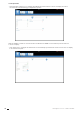
• Email This tab allows you to activate and configure email notifications in case of alarms: Activation: enable/disable the SMTP email export function Host: enter the IP address or name of the SMTP server Port: enter the SMTP port Secured connection: enable or disable the secured connection (SMTPS) Activate Authentication: enable or disable the SMTP authentication. It is possible to activate the authentication, even if the secured connection is disabled.
10.3. Cyber security profile In addition to the rights of the Admin profile, the Cyber security profile allows you to: - Manage all profiles and change their passwords. The Cyber security profile it also allows to generate the passphrase for password recovery. - Implement a Cyber Security policy from a dedicated menu: 10.3.1. Cyber security menu The Cyber Security menu allows you to: - Define a custom security policy. - Secure the client-server communication (HTTPS, FTPS, SMTPS).
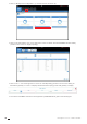
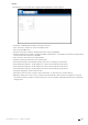
.3.2. “Security Policy” tab DIRIS Digiware D-50/D-70 displays can reduce the attack exposure by disabling certain peripherals or services that are not essential to the customer’s use case. Peripherals - USB: disable the USB port of the D-50/D-70 display. - Bluetooth Low Energy: disable the Bluetooth Low Energy of the D-50/D-70 display. - Modbus slave over RS485: authorise or disable Modbus communication on the RS485 port of the D-50/D-70 display.
10.3.3. “HTTPS” tab The HTTPS tab allows you to upload a digital certificate to secure the web navigation: The D-50/D-70 displays will accept a digital certificate under the .pem format. Once a digital certificate and private key has been uploaded, you can edit HTTPS settings to secure the web navigation. • The D-50/D-70 displays are compatible with RSA and ECDSA (Elliptic Curve Digital Signature Algorithm) digital certificates.
10.3.5. “Firewall” tab This tab allows you to implement a firewall to protect against Denial-Of-Service attacks also called Flooding attacks by entering a max bandwidth in kbit/s and a max number of requests per second: A client exceeding one of the above parameters while communicating to the DIRIS Digiware D-50/D-70 display will be blocked for 30 seconds. 10.3.6.
Go to the “Upgrade” tab: Upload the desired firmware package (.dfu file) by clicking on the “Browse” button.
10.4. WEBVIEW-M For more information on the visualisation of measurement data, please refer to the WEBVIEW-M instruction manual, available on the Socomec website at the following link: https://www.socomec.com/range-software-solutions_en.html?product=/webview_en.
11. ALARMS DIRIS Digiware D-50 and D-70 displays collect alarms from downstream devices connected on the Digiware or RS485 bus. DIRIS Digiware D-50 and D-70 displays also support 8 System alarms. The types of system alarms and the possible causes are listed in the table below: System alarm # System alarm 1 Alarm type Email transmission error Description Triggered if the D-50/D-70 display could not send the notification email in case of an alarm.
12. USE Once the loads are configured, you can visualise the measurements of each load from the "MEASURES" menu. You can view active and finished alarms from the "EVENTS" menu. HOME | LOADS MEASURES INPUTS/OUTPUTS PROTECTION EVENTS PARAMETERS ... If the "ALARM" LED of the D-50/D-70 display is lit, stable or flashing, it means there is at least one active alarm. Go to the "EVENTS" menu to see which alarms are active. HOME | LOADS MEASURES INPUTS/OUTPUTS PROTECTION EVENTS ...
13. DIRIS DIGIWARE D-50/D-70 TECHNICAL CHARACTERISTICS 13.1. Mechanical characteristics Type of screen Capacitive touch-screen technology, 10 keys Screen resolution 350 x 160 pixels Front panel protection index IP65* (IEC 60529) Weight DIRIS Digiware D-50 / D-70 210 g * Front face only. The use of a silicone seal may be required to ensure sufficient sealing of the junction between D-50/D-70 display and panel door. 13.2.
13.3.2. USA “This device complies with part 15 of the FCC Rules. Operation is subject to the following two conditions: (1) This device may not cause harmful interference, and (2) this device must accept any interference received, including interference that may cause undesired operation.” (§15.19 (3)) FCC Caution: Any changes or modifications not expressly approved by the party responsible for compliance could void the user’s authority to operate this equipment.
13.6.
Annex I. SNMP COMWMUNICATION WITH THE DIRIS DIGIWARE D-50 / D-70 Annex I - 1. SNMP generalities SNMP stands for Simple Network Management Protocol and is widely used by administrators for an easy network monitoring of devices on IP networks. It works in a client-server communication mode on an Ethernet physical layer. Once enabled from the Easy Config configuration software, the DIRIS Digiware D-70 display supports SNMP v1, v2 and v3.
Traps are sent automatically when the alarm occurs. They will be sent again once the “Trap report frequency” time (entered in Easy Config) is elapsed. The alarm must be activated in the product (using the configuration software Easy Config) in order for the Traps to be sent. Traps can either be configured for specific hosts or “broadcast” to the whole network. Up to two server IP addresses can be entered in Easy Config for SNMP trap notification of specific hosts. Annex I - 3.
Annex I - 5. Retrieving data using the DIRIS Digiware D-50 / D-70 MIB file The DIRIS Digiware D-50 / D-70 is compliant with MIB-II defined by the MIB standard RFC 1213 which defines the following structure: Root iso (1) org (3) dod (6) Internet (1) directory (1) mgm (2) experimental (3) mib-2 (1) system (1) interfaces (2) private (4) enterprise (1) ip (4) vendor X (2) vendor Y (9) SOCOMEC (4555) OID Tree Example The standard branches are under the same parent branch structure: 1.3.6.1.4.
Example: Let us consider the following architecture: D-50/D-70 PRODUCT I-30 I-30 MODBUS ADDRESS 4 5 Load 1: 3P + N - 3CT Load 1: 1P + N - 1CT Load 2: 1P + N - 1CT Load 3: 1P + N - 1CT LOAD TYPE Digiware bus U-30 I-30 I-30 @3 @4 @5 The final OID to get the instantaneous current I1 for the I-30 module @ Modbus address 4 for load 1 is: 1.3.6.1.4.1.4555.10.20.20.1.10000.4.1 For the I-30 module @ address 5, there are multiple loads configured.
Annex I - 6. SNMP configuration via Easy Config System After logging in to Easy Config System on the DIRIS Digiware D-50 / D-70, you can find the SNMP settings in the SNMP menu, under SNMP settings: • Community configuration SNMP V1 & V2: - SNMP V1 Read Community: Read-only community string for SNMP v1. Default community string is “public”. It allows a manager to retrieve read-only data from a device connected to the DIRIS Digiware D-50 / D-70.
Annex II. BACNET COMMUNICATION WITH THE DIRIS DIGIWARE D-50 / D-70 The DIRIS Digiware D-50 / D-70 supports the BACnet IP protocol. It acts as a BACnet IP gateway to all devices compatible and connected downstream via RS485 or the Digiware Bus. The PICS (Protocol Implementation Conformance Statement) of the DIRIS Digiware D-50 / D-70 is available on the Socomec website at www.socomec.com. Annex II - 1.
A list of properties defines each BACnet Object. Properties can be: • Required by the BACnet specification. • Optional. In this case, vendors can choose whether to implement them for their devices. • Proprietary. Vendors can add their own created properties. Device Object: Every BACnet device compatible with the DIRIS Digiware D-50 / D-70 must have the Device Object and its associated required properties that fully describe the BACnet device to the network.
The way the OID is assigned to a device (instance number) is the following: OID = Main OID (= default 100) + ModbusAddress: • Device with Main OID (100) is the DIRIS Digiware D-50 / D-70 display itself. • The device with OID (1xx) is the device with the Modbus address xx. Analog Input Object: The DIRIS Digiware D-50 / D-70 acts as a BACnet gateway. It provides a number of Analog Input objects which may be available from the devices compatible and connected to the DIRIS Digiware D-50 / D-70.
Energies Total + Partial + LastPartial Average Min/Max + Timestamp Unsigned • • 1 VystPhPh System Ph-Ph Voltage V Unsigned • • 2 CurrentSyst System Current A Unsigned • • 3 Frequency System Frequency Hz Unsigned • • • • • 4 VoltPhNV1 Ph-N Voltage V1 V Unsigned • • • • • 5 VoltPhNV2 Ph-N Voltage V2 V Unsigned • • • • • 6 VoltPhNV3 Ph-N Voltage V3 V Unsigned • • • • • 7 VoltPhNVn Ph-N Voltage Vn V Unsigned • • • • • 8 VoltPhPhU12 Ph-Ph Vol
Energies Total + Partial + LastPartial Average Min/Max + Timestamp • • • • • 35 PowerFactorPF1 PF1 Power Factor - Signed • • • • • 36 PowerFactorTypeSPF1 sPF1 Power Factor Type - Unsigned • • • • • 37 PowerFactorPF2 - Signed • • • • • 38 PowerFactorTypeSPF2 sPF1 Power Factor Type - Unsigned • • • • • 39 PowerFactorPF3 - Signed • • • • • 40 PowerFactorTypeSPF3 sPF1 Power Factor Type - Unsigned • • • • • 41 LoadCurve_ P+ Load Curve Positive Activ
Annex II - 3. BACnet Services The services define methods for BACnet devices to communicate and exchange data with one another.