INSTALLATION AND OPERATING MANUAL EN DIRIS Digiware D-50 & D-70 v2 Display and power supply interface
EN CONTENTS 1. DOCUMENTATION. . . . . . . . . . . . . . . . . . . . . . . . . . . . . . . . . . . . . . . . . . . . . . . . . . . . . . . . . . . . . . . . . . . 4 2. HAZARDS AND WARNINGS. . . . . . . . . . . . . . . . . . . . . . . . . . . . . . . . . . . . . . . . . . . . . . . . . . . . . . . . . . . . 5 2.1. Risk of electrocution, burns or explosion. . . . . . . . . . . . . . . . . . . . . . . . . . . . . . . . . . . . . . . . . . . . . . . . 5 2.2. Risk of damaging the device. . . . . . . . . . . .
10. WEBSERVER EMBEDDED IN THE D-50/D-70 DISPLAYS. . . . . . . . . . . . . . . . . . . . . . . . . . . . . . . . . . . 35 10.1. User profiles . . . . . . . . . . . . . . . . . . . . . . . . . . . . . . . . . . . . . . . . . . . . . . . . . . . . . . . . . . . . . . . . . . . 35 10.2. Admin profile. . . . . . . . . . . . . . . . . . . . . . . . . . . . . . . . . . . . . . . . . . . . . . . . . . . . . . . . . . . . . . . . . . . 37 10.2.1. “Devices” tab . . . . . . . . . . . . . . . . . . . . . . . . . . .
1. DOCUMENTATION All documentation on DIRIS Digiware D-50 and D-70 is available on the SOCOMEC website: www.socomec.
2. HAZARDS AND WARNINGS The term "device" used in this document covers both DIRIS Digiware D-50 and D-70. The assembly, use, servicing and maintenance of this equipment must only be carried out by trained, qualified professionals. SOCOMEC shall not be held responsible for failure to comply with the instructions in this manual. 2.1.
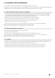
3. PRELIMINARY OPERATIONS To ensure the safety of personnel and the product, please carefully read the contents of these instructions before installation. Check the following points as soon as you receive the package containing the device: • The packaging is in good condition • The device has not been damaged during transportation • The device reference number conforms to your order • The packaging includes the device fitted with removable terminal blocks and a Quick start guide. 4.
• Device security: Device security depends on its network environment, but also user behaviour. In terms of the environment, elementary protective measures (filtering authorised stations by MAC address, opening service ports, selecting authorised applications etc.) are highly recommended. Greater precaution is required on managing removable media (external hard drive, USB flash drive, wireless communication provision etc.).
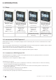
5. INTRODUCTION 5.1. Range DIRIS Digiware D-50 Multipoint display DIRIS Digiware D-50 BLE Multi-point display with Bluetooth Low Energy DIRIS Digiware D-70 Multipoint display Ref. 4829 0204 Ref. 4829 0206 Ref.
5.2.2. Introduction to DIRIS Digiware D-70 The DIRIS Digiware D-70 display embeds a web-based software (WEBVIEW-M) which allows a remote visualisation of real-time and historical measurements. The DIRIS Digiware D-70 display is a master on the Digiware bus and acts as a gateway interface to communicate measurements over RS485 and Ethernet. The RS485 port can be configured as a Master or Slave. The Ethernet port is used to: • Communicate via Modbus TCP (max.
PC Ethernet Digiware bus Digiware Bus Termination RS485 120 Ω DIRIS Digiware D-50/D-70 120 Ω DIRIS DIRIS B COUNTIS 5.3.
5.4.
5.6. Menu structure LOADS VOLTAGES CURRENTS MEASURES POWERS ENERGIES INPUT/OUTPUT PULSE METERS RESET ALL MIN/MAX VALUES DIGITAL INPUT DIGITAL OUPUT ANALOGUE INPUT Load Line-Neutral Load Line-Line Net. Frequency Net. Line-Neutral Net. Line-Neutral Unbalance Net. Line-Neutral Harmonics Net. Line-Neutral Crest Factor Net. Line-Line Net. Line-Line Unbalance Net. Line-Line Harmonics Net.
5.7. Dimensions 92 Dimensions in/mm 92 31 16 Door cut-out must be 92x92mm.
6. MOUNTING 6.1. Recommendations and safety Refer to the safety instructions (section “2. Hazards and warnings”, page 5) 6.2. Door mounting DIRIS Digiware D-50 and D-70 are panel-mounted (cut-out: 92x92mm). The display is secured with clips. 3.62 +0.0 92 +0.8 3 3.78 96 3.62+0.03 -0 92+0.8 -0 1.22 31 3.78 96 14 EN 0.63 16 0.03 Max .
6.3. DIN rail mounting DIRIS Digiware D-50 and D-70 can also be mounted on a DIN rail using a dedicated accessory (4829 0230) sold separately.
7. COMMUNICATION ARCHITECTURES The DIRIS Digiware D-50 and D-70 display can be configured as a Slave or a Master for the RS485 bus. Ethernet Ethernet Digiware Bus NC DIRIS Digiware D-50 / D-70 LIYCY-CY MASTER SUPPLY RS485 Digiware Ethernet 7.1. RS485 Master Digiware Bus 24 VDC* (20 W max) 24 V 24 VDC RS485 (20 W max) 120 Ω (*) T he use of a 1A / 24 VDC fuse protection is recommended if the 24 VDC power supply is not provided by Socomec.
8. CONFIGURATION From the Socomec start-up sreen, press “OK” to enter the navigation menu: ID: E5C801 Select the "PARAMETERS" menu by using the navigation key "DOWN ARROW" 3x and confirm with "OK”: HOME | LOADS MEASURES INPUTS/OUTPUTS PROTECTION EVENTS PARAMETERS ... Enter the password "100" using the arrow pad (4 arrow keys) and confirm with "OK": HOME | LOADS MEASURES INPUTS/OUTPUTS PROTECTION EVENTS CODE: 100 PARAMETERS ...
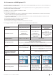
The 3 following menus will be detailed in the paragraphs below: PARAMETERS | DISPLAY CONFIGURE A DEVICE AUTODETECT SERIAL DEVICES LIST PRODUCTS ADD NEW DEVICE … • DISPLAY: to access settings that are specific to the display. • AUTODETECT SERIAL DEVICES: to launch an automatic detection and addressing of meters and power monitoring devices connected to the D-50/D-70 display. • CONFIGURE A DEVICE: to configure the meters and other power monitoring devices connected to the D-50/D-70 display. 8.1.
8.1.1. Language You can change the display's navigation language here. Choose from: English, French, German, Italian, Spanish, Flemish, Polish, Turkish, Russian, Solvenian and Chinese. Select your language with the arrow pad and confirm with "OK". PARAMETERS | ENGLISH FRANCAIS DEUTSCH ITALIANO POLSKI … 8.1.2. Date format You can select the display's date format, including the separator between the day, month and year: DATE FORMAT | DATE FORMAT: MM/DD/YYYY DATE SEPARATOR: / 8.1.3.
8.1.4. Ethernet communication You can configure the Ethernet settings of DIRIS Digiware D-50 / D-70 displays: • DHCP (IP address dynamically assigned by the Ethernet network) ENABLED/DISABLED • IP address • Subnet mask • LAN gateway PARAMETERS | DHCP DISABLED IP ADDRESS 192.168.000.003 MASK 255.255.255.000 GATEWAY 000.000.000.000 8.1.5.
8.2. Automatic detection of slave devices The auto-discovery function scans and discovers slave devices connected to the Digiware and RS485 buses and automatically assigns a unique Modbus address to each device. The auto-discovery function is compatible with DIRIS Digiware modules, DIRIS B and DIRIS A-40 power meters. For other devices such as COUNTIS energy meters and DIRIS A-10/A-20/A-30/A-60 power meters, you must change their Modbus address manually. Example of auto-discovery on a D-50/D-70 display.
This allows you to allocate Modbus addresses to the connected devices within a specific range: | AUTODETECT. START ADDRESS 001 END ADDRESS 247 NB ADDR. POSSIBLE 032 ADDR. SET METHOD AUTO SET APPLY SETTINGS Choose the conflict resolution method (“ADDR. SET METHOD”): - “PUSH BUTTON”: you must press the push button on each module to resolve address conflicts. The order you will use to press the push buttons on the modules will also determine the order for the Modbus addressing of those modules.
Please be aware that this removes all previously found devices (if they are still there they will be found again). AUTODETECT. | WARNING: AUTODETECT WILL REMOVE ALL DEVICES ALREADY PRESENT! PRESS OK TO CONTINUE. PRESS BACK TO CANCEL. After pressing "OK", the steps below will automatically follow: • ADDRESS DETECTION AUTODETECT. | STATUS ADDR DETECTION FOUND / CONFLICT 000 / 000 DIGIWARE ADDRESSING RANGE 001:247 METHOD FAST STOP • ADDRESS SCANNING AUTODETECT.
If you have chosen a manual address conflict resolution ("PUSH BUTTON"), there will be one or several conflicts if multiple devices have the same Modbus address. A pop-up message will be displayed on the HMI: AUTODETECT. | ADDRESS CONFLICTS DETECTED! PRESS THE AUTOADDRESS BUTTON ON ALL NON-BLINKING DEVICES TO SOLVE THE CONFLICTS. To manually resolve address conflicts, locate the devices which have a lit and stable "COM" LED. Press and hold down the addr.
D-50 / D-70 @2 Digiware bus U-30 I-30 I-30 I-30 @3 @4 @5 @6 You can then check the list of detected products along with their Modbus addresses in the “LIST PRODUCTS” menu: PARAMETERS | LOAD1 | LOAD1 DISPLAY CONFIGURE A DEVICE AUTODETECT SERIAL DEVICES LIST PRODUCTS ADD NEW DEVICE … Example: LIST PROD.
You can find the IDs on the marking on the products (546434 on the U-30 and F0C1D2 on one of the I-30s) as shown in the picture below: You can now perform the configuration of the system. Each product must be configured individually. 8.3. Configuring the DIRIS Digiware system from the D-50/D-70 display Go to "Parameters" > "Configure a device".
Electrical network settings are configured from the DIRIS Digiware U-xx module. LIST PROD. | I-30@4 ID:FOC1D2 @004 U-30@6 ID:546434 @006 | SELECT PROD. U-30@6 ID:546434 NETWORK Load settings are configured from DIRIS Digiware I-xx modules SELECT PROD.. | I-30@4 ID:FOC1D2 @004 U-30@6 ID:546434 @006 SELECT PROD. | I-30@4 ID:FOC1D2 LOADS With DIRIS B power monitoring devices, network and loads settings are accessible from the DIRIS B altogether.
8.3.1. Network configuration You can configure the various network voltage parameters: • Network type: single-phase (1P+N), two-phase (2P), three-phase without neutral (3P), three-phase+neutral (3P+N) • Nominal voltage: This is the phase-phase voltage (usually 400 V) for three-phase networks This is the phase-neutral voltage (usually 230 V) for single-phase networks • Nominal frequency: 50 or 60 Hz depending on the country • Phase rotation: V1-V2-V3 (Direct) or V1-V3-V2 (reverse).
| LOAD I-30@4 ID:FOC1D2 INPUT I01 I02 I03 250 A 250 A 250 A +/DIRECT +/DIRECT +/DIRECT LINE V V3 V2 V1 LOAD L1 L1 L1 CT WAY TYPE 3P+N_3CT 3P+N_3CT 3P+N_3CT PRESS OK TO ENTER SETTINGS The 3 current inputs I01, I02, I03 are assigned to the same three-phase load no. 1 (L1).
8.3.2.2. Changing the load settings Following the example above, to change the settings, press "OK".
| LINE SETTINGS I-30@4 ID:FOC1D2 WAY +/DIRECT V LINE V3 CT 0600 DETECT OK If a load is configured as three-phase or three-phase+neutral, for example, you would have to configure multiple current sensors (e.g.
9. CONFIGURATION VIA EASY CONFIG SYSTEM The Easy Config System software can be downloaded from the Socomec website at the following link: www.socomec.com/easy-config-system_en.html The Configuration of the DIRIS Digiware D-50/D-70 display and downstream Socomec devices can be done from the Easy Config System software, by connecting a computer to the D-50/D-70 display either via USB or via Ethernet. 9.1.
Ethernet 9.2. Ethernet connection mode Easy Config System Digiware Bus DIRIS Digiware D-xx - - Digiware system DIRIS B RS485 Open Easy Config System. Log in as User or Admin. Admin default password is “Admin”. Click on “New configuration”, enter a name and icon. Click on the newly created configuration. Click on the “+” icon to manually add the D-50/D-70 display to the topology, by selecting the product, entering the IP address, Modbus address.
- O nce the slave auto-discovery process is finished, slave devices will be displayed in the lower part of the dashboard menu (2). The number of devices accessible downstream the D-50/D-70 display is also displayed in the “Organisation” part, next to the D-50/D-70 display.
10. WEBSERVER EMBEDDED IN THE D-50/D-70 DISPLAYS A webserver is embedded for the configuration of network parameters (WEB-CONFIG, D-50/D-70) and the remote visualisation of measurement data (WEBVIEW-M, D-70 only). To connect to the gateway’s webserver, enter its IP address in the address bar of your web browser. Default Ethernet parameters of the DIRIS Digiware D-50/D-70 displays are as follows: - IP address: 192.168.0.4 - Mask: 255.255.255.0 - Gateway: 192.168.0.1 10.1.