IB810 Full-Size Socket 478 Pentium 4 Intel 845 CPU Card USER’S MANUAL Version 1.
Acknowledgments Award is a registered trademark of Award Software International, Inc. PS/2 is a trademark of International Business Machines Corporation. Intel and Pentium 4 are registered trademarks of Intel Corporation. Microsoft Windows is a registered trademark of Microsoft Corporation. Winbond is a registered trademark of Winbond Electronics Corporation. All other product names or trademarks are properties of their respective owners.
Table of Contents Introduction ........................................................1 Product Description ..........................................................1 Checklist...........................................................................2 Specifications....................................................................3 Board Dimensions.............................................................4 Installations ........................................................5 Installing the CPU...
This page is intentionally left blank.
INTRODUCTION Introduction Product Description The IB810 Pentium 4 Full Size PICMG CPU Card incorporates the Intel® advanced 845 Chipset Memory Controller hub and supports 478-pin Intel Pentium 4 processors of 1.3GHz and up to 2GHz. This CPU card represents the perfect choice for those who want superior performance for rugged and demanding applications in industrial automation, image processing, multimedia and telecommunications.
INTRODUCTION Checklist Your IB810 package should include the items listed below.
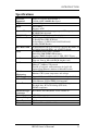
INTRODUCTION Specifications Processor Supported Chipset BIOS Socket 478 support Intel Pentium 4 1.3GHz~2GHz, 400MHz Bus Speed Intel 845 Chipset Award BIOS Supports ACPI System Memory 2x DDR memory sockets support up to 2GB capacity PC200/PC266 supported LPC I/O Chipset ITE IT8712 (keyboard controller is built-in) I/O Features 1x FDD (up to 2.
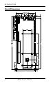
INTRODUCTION Board Dimensions 4 IB810 User’s Manual
INSTALLATIONS Installations This section provides information on how to use the jumpers and connectors on the IB810 in order to set up a workable system. The topics covered are: Installing the CPU.............................................................6 ATX Power Installation ....................................................7 MicroPCI Daughter Card Installation ................................7 Installing the Memory .......................................................8 Setting the Jumpers......
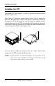
INSTALLATIONS Installing the CPU The IB810 CPU Card supports a Socket 478 processor socket for Intel Pentium 4 processors. The Socket 478 processor socket comes with a lever to secure the processor. Raise this lever to about a 90° angle to allow the insertion of the processor. Place the processor into the socket by making sure the notch on the corner of the CPU corresponds with the notch on the inside of the socket. Once the processor has slide into the socket, return the lever to the lock position.
INSTALLATIONS ATX Power Installation Power is provided to the IB810 CPU card with the J2 and J12 ATX power connectors. Please note that the J12 external ATX power connector should be connected to the backplane for IB810 to function. J12 is located below the IDE connector. Please refer to the figure below. MicroPCI Daughter Card Installation The IB810 CPU card is integrated with a MicroPCI socket that uses SO-DIMM 144-pin connectors. These sockets can accommodate the optional MicroPCI daughter cards.
INSTALLATIONS Installing the Memory The IB810 CPU Card supports two DDR memory sockets for a maximum total memory of 2GB in DDR memory type. The memory module capacities supported are 64MB, 128MB, 256MB, 512MB and 1GB. Installing and Removing Memory Modules To install the DDR modules, locate the memory slot on the CPU card and perform the following steps: 1. Hold the DDR module so that the two keys of the DDR module align with those on the memory slot. 2.
INSTALLATIONS Setting the Jumpers Jumpers are used on IB810 to select various settings and features according to your needs and applications. Contact your supplier if you have doubts about the best configuration for your needs. The following lists the connectors on IB810 and their respective functions. Jumper Locations on IB810............................................................. 10 Configuring the CPU Frequency .....................................................
INSTALLATIONS Jumper Locations on IB810 JP10, JP11, JP12, JP13, JP14: CRT VGA Signal Select JP2, JP3, JP4: RS232/422/485 (COM2) Selection JP1: DiskOnChip Address Select JP8: LVDS Panel Power Select JP7: Clear CMOS Contents SW1: LVDS Resolution Select 10 IB810 User’s Manual
INSTALLATIONS Configuring the CPU Frequency The IB810 CPU card does not provide DIP switches to configure the processor speed (CPU frequency). However, the processor speed can be automatically detected by the system. JP1: DiskOnChip Address Select JP1 Address D0000-D7FFF D8000-DFFFF (default) JP2, JP3, JP4: RS232/422/485 (COM2) Selection COM1 is fixed for RS-232 use only. COM2 is selectable for RS232, RS-422 and RS-485. The following table describes the jumper settings for COM2 selection.
INSTALLATIONS JP7: Clear CMOS Contents Use JP7, a 3-pin header, to clear the CMOS contents. Note that the ATX-power connector should be disconnected from the CPU card before clearing CMOS. JP7 Setting Function Pin 1-2 Short/Closed Normal Pin 2-3 Short/Closed Clear CMOS JP8: LVDS Panel Power Select JP8 Power 3.
INSTALLATIONS This page was intentionally left blank.
INSTALLATIONS [ Connectors on IB810 The connectors on IB810 allows you to connect external devices such as keyboard, floppy disk drives, hard disk drives, printers, etc. The following table lists the connectors on IB810 and their respective functions. Connector Locations on IB810........................................................ 15 J1: System Function Connector....................................................... 16 J2: ATX 12V/+12V Power Connector............................................
INSTALLATIONS Connector Locations on IB810 J27: 2nd RJ45 Connector J26: VGA CRT Connector J25: Primary RJ45 Connector J23: PS/2 KB and Mouse Conn.
INSTALLATIONS J1: System Function Connector J1 provides connectors for system indicators that provide light indication of the computer activities and switches to change the computer status. J1 is a 20-pin header that provides interfaces for the following functions. Hard Disk Drive LED Reset Switch Turbo LED Connector ATX Power On Switch SMI / Hardware Switch Power LED Speaker Speaker: Pins 1 - 4 This connector provides an interface to a speaker for audio tone generation. An 8-ohm speaker is recommended.
INSTALLATIONS SMI/Hardware Switch: Pins 6 and 16 This connector supports the "Green Switch" on the control panel, which, when pressed, will force the system into the power-saving mode immediately. Pin # 6 16 Signal Name Sleep Ground ATX Power ON Switch: Pins 7 and 17 This 2-pin connector is an “ATX Power Supply On/Off Switch” on the system that connects to the power switch on the case. When pressed, the power switch will force the system to power on.
INSTALLATIONS Hard Disk Drive LED Connector: Pins 10 and 20 This connector connects to the hard drive activity LED on control panel. This LED will flash when the HDD is being accessed.
INSTALLATIONS IDE2 IDE2: Secondary IDE Connector Signal Name Pin # Pin # Reset IDE 1 2 Host data 7 3 4 Host data 6 5 6 Host data 5 7 8 Host data 4 9 10 Host data 3 11 12 Host data 2 13 14 Host data 1 15 16 Host data 0 17 18 Ground 19 20 DRQ1 21 22 Host IOW 23 24 Host IOR 25 26 IOCHRDY 27 28 DACK1 29 30 IRQ15 31 32 Address 1 33 34 Address 0 35 36 Chip select 0 37 38 Activity 39 40 Signal Name Ground Host data 8 Host data 9 Host data 10 Host data 11 Host data 12 Host data 13 Host data 14 Host data 15 Prote
INSTALLATIONS FAN3: Auxiliary Fan Power Connector FAN3 is a 3-pin header for a 12V fan. Pin # 1 2 3 Signal Name Ground +12V Rotation detection J4: Floppy Drive Connector J4 is a 34-pin header and will support up to 2.88MB floppy drives.
INSTALLATIONS J5: Parallel Port Connector The following table describes the pin out assignments of this connector.
INSTALLATIONS J8, J9: COM1, COM2 Serial Port J8 and J9, both 10-pin headers, are the onboard serial port connectors. J8 fixed as RS-232 J9 Configurable as RS-232/ RS-422/485 with jumpers JP2/JP3/JP4 Pin # 1 2 3 4 5 6 7 8 9 10 Signal Name RS-232 DCD RX TX DTR GND DSR RTS CTS RI NC RS-422 TXTX+ RX+ RXGND RTSRTS+ CTS+ CTSNC RS-485 DATADATA+ NC NC GND NC NC NC NC NC J10: TV-Out Connector The TV-Out connector is used together with the optional ID120 daughter card to support the function.
INSTALLATIONS J11, J16: LVDS Connectors (2nd channel, 1st channel) The LVDS connectors are composed of the first channel (J16) and second channel (J11) to support 24-bit or 48-bit. Signal Name Pin # Pin # Signal Name TX0Ground TX15V/3.3V TX3TX2Ground TXC5V/3.
INSTALLATIONS J12: External ATX Power Connector Pin # 1 2 3 Signal Name Ground PS-ON (soft on/off) 5VSB (Standby +5V) J14: External Audio Connector J14 is a 12-pin header that is used to connect to the ID120 daughter card that integrates jacks for Line In, Line Out and Speaker.
INSTALLATIONS J18, J19: USB Connectors The following table shows the pin outs of the USB pin headers connectors. Overall, the two pin headers support four USB ports. J18 Signal Name Vcc USB0USB0+ Ground Pin 1 2 3 4 Pin 5 6 7 8 Signal Name Ground USB1+ USB1Vcc J19 Signal Name Vcc USB2USB2+ Ground Pin 1 2 3 4 Pin 5 6 7 8 Signal Name Ground USB3+ USB3Vcc J20: Smart Card Reader Interface J20 is a 14-pin header that provides interface for a Smart Card Reader.
INSTALLATIONS J21: IrDA Connector J21 is used for an optional IrDA connector for wireless communication. Pin # Signal Name 1 +5V 2 No connect 3 Ir RX 4 Ground 5 Ir TX J22: External PS/2 Keyboard and Mouse Connector Pin # 1 2 3 4 5 6 Signal Name Mouse data KB data Ground Vcc Mouse Clock KB Clock Please take note of the pin number orientation of this connector to avoid possible damage to the keyboard due to wrong insertion.
INSTALLATIONS J23: PS/2 Keyboard and Mouse Connector J23 uses a Y-cable with dual D-connectors for a PS/2 keyboard and a PS/2 mouse. Pin # 1 2 3 4 5 6 J12 Signal Name Mouse data Keyboard data Ground Vcc Mouse Clock Keyboard Clock J25, J27: Primary and Secondary RJ45 Connector J25 and J27 are the primary RJ-45 and secondary RJ-45 connectors respectively. The J27 secondary RJ-45 connector is used in conjunction with a secondary Ethernet provided through a MicroPCI Ethernet card.
BIOS SETUP BIOS Setup This chapter describes the different settings available in the Award BIOS that comes with the CPU card. The topics covered in this chapter are as follows: BIOS Introduction ........................................................................ 29 BIOS Setup ..................................................................................... 29 Standard CMOS Setup ................................................................. 31 Advanced BIOS Features ...........................
BIOS SETUP BIOS Introduction The Award BIOS (Basic Input/Output System) installed in your computer system’s ROM supports Intel Pentium 4 processors. The BIOS provides critical low-level support for a standard device such as disk drives, serial ports and parallel ports. It also adds virus and password protection as well as special support for detailed fine-tuning of the chipset controlling the entire system.
BIOS SETUP CMOS Setup Utility – Copyright © 1984-2001 Award Software Standard CMOS Features Advanced BIOS Features Advanced Chipset Features Integrated Peripherals Power Management Setup PnP/PCI Configurations PC Health Status Frequency/Voltage Control Load Fail-Safe Defaults Load Optimized Defaults Set Supervisor Password Set User Password Save & Exit Setup Exit Without Saving ESC : Quit F10 : Save & Exit Setup á â à ß : Select Item Time, Date, Hard Disk Type… The section below the setup items of the
BIOS SETUP Standard CMOS Setup “Standard CMOS Setup” choice allows you to record some basic hardware configurations in your computer system and set the system clock and error handling. If the CPU card is already installed in a working system, you will not need to select this option. You will need to run the Standard CMOS option, however, if you change your system hardware configurations, the onboard battery fails, or the configuration stored in the CMOS memory was lost or damaged.
BIOS SETUP Time The time format is: Hour : 00 to 23 Minute : 00 to 59 Second : 00 to 59 To set the time, highlight the “Time” field and use the / or +/- keys to set the current time. IDE Primary HDDs / IDE Secondary HDDs The onboard PCI IDE connectors provide Primary and Secondary channels for connecting up to four IDE hard disks or other IDE devices. Each channel can support up to two hard disks; the first is the “Master” and the second is the “Slave”.
BIOS SETUP Video This field selects the type of video display card installed in your system. You can choose the following video display cards: EGA/VGA For EGA, VGA, SEGA, SVGA or PGA monitor adapters. (default) CGA 40 Power up in 40 column mode. CGA 80 Power up in 80 column mode. MONO For Hercules or MDA adapters. Halt On This field determines whether or not the system will halt if an error is detected during power up. No errors The system boot will not be halted for any error that may be detected.
BIOS SETUP Advanced BIOS Features This section allows you to configure and improve your system and allows you to set up some system features according to your preference.
BIOS SETUP First/Second/Third Boot Device These fields determine the drive that the system searches first for an operating system. The options available include Floppy, LS/ZIP, HDD-0, SCSI, CDROM, HDD-1, HDD-2, HDD-3, LAN and Disable. Boot Other Device These fields allow the system to search for an operating system from other devices other than the ones selected in the First/Second/Third Boot Device. Swap Floppy Drive This item allows you to determine whether or not to enable Swap Floppy Drive.
BIOS SETUP Security Option This field allows you to limit access to the System and Setup. The default value is Setup. When you select System, the system prompts for the User Password every time you boot up. When you select Setup, the system always boots up and prompts for the Supervisor Password only when the Setup utility is called up. APIC Mode APIC stands for Advanced Programmable Interrupt Controller. The default setting is Enabled.
BIOS SETUP Advanced Chipset Features This Setup menu controls the configuration of the chipset.
BIOS SETUP DRAM Data Integrity Mode This BIOS setting is used to configure your RAM's data integrity mode. ECC stands for Error Checking and Correction and it should only be used if you are using 72-bit ECC RAM. This will enable the system to detect and correct single-bit errors. It will also detect double-bit errors though it will not correct them. This provides increased data integrity and system stability at the expense of a little speed.
BIOS SETUP Delay Prior to Thermal This field activates the CPU thermal function after the systems boots for the set number of minutes. The options are 16Min and 64Min. AGP Aperture Size The field sets aperture size of the graphics. The aperture is a portion of the PCI memory address range dedicated for graphics memory address space. Host cycles that hit the aperture range are forwarded to the AGP without any translation. The default setting is 64M.
BIOS SETUP Integrated Peripherals This section sets configurations for your hard disk and other integrated peripherals.
BIOS SETUP IDE Primary/Secondary Master/Slave UDMA These fields allow your system to improve disk I/O throughput to 33Mb/sec with the Ultra DMA/33 feature. The options are Auto and Disabled. USB Controller The options for this field are Enabled and Disabled. By default, this field is set to Enabled. USB Keyboard Support The options for this field are Enabled and Disabled. By default, this field is set to Disabled. AC97 Audio The default setting of the AC97 Audio is Auto.
BIOS SETUP UART Mode Select This field determines the UART 2 mode in your computer. The default value is Normal. Other options include IrDA and ASKIR. UR2 Duplex Mode This field allows you to choose between Half Duplex and Full Duplex mode. Parallel Port Mode This field allows you to determine parallel port mode function.
BIOS SETUP Power Management Setup The Power Management Setup allows you to save energy of your system effectively.
BIOS SETUP Power Management This field allows you to select the type of power saving management modes. There are four selections for Power Management. Min. Power Saving Minimum power management Max. Power Saving Maximum power management. User Define Each of the ranges is from 1 min. to 1hr. Except for HDD Power Down which ranges from 1 min. to 15 min.
BIOS SETUP Video Off Method This field defines the Video Off features. There are three options. V/H SYNC + Blank Default setting, blank the screen and turn off vertical and horizontal scanning. DPMS Allows BIOS to control the video display. Blank Screen Writes blanks to the video buffer. Video Off In Suspend When enabled, the video is off in suspend mode. The default setting is Yes. Suspend Type The default setting for the Suspend Type field is Stop Grant.
BIOS SETUP Reload Global Timer Events The HDD, FDD, COM, LPT Ports, and PCI PIRQ are I/O events which can prevent the system from entering a power saving mode or can awaken the system from such a mode. When an I/O device wants to gain the attention of the operating system, it signals this by causing an IRQ to occur. When the operating system is ready to respond to the request, it interrupts itself and performs the service.
BIOS SETUP PNP/PCI Configurations This option configures the PCI bus system. All PCI bus systems on the system use INT#, thus all installed PCI cards must be set to this value. CMOS Setup Utility – Copyright © 1984-2001 Award Software PnP/PCI Configurations PNP OS Install No Reset Configuration Data Disabled Menu Level ITEM HELP Resources Controlled By Auto (ESCD) IRQ Resources Press Enter DMA Resources Press Enter PCI/VGA Palette Snoop Disabled Default is Disabled.
BIOS SETUP PC Health Status This section shows the parameters in determining the PC Health Status. These parameters include temperatures, fan speeds and voltages. CMOS Setup Utility – Copyright © 1984-2001 Award Software PC Health Status Shutdown Temperature Vcore (V) Disabled 1.63V +1.8(V) 1.79V VCC3(V) 3.37V +5(V) 5.05V +12(V) 12.09V -12(V) (-)12.03V 5VSB(V) 5.05V Voltage Battery 3.24V System Temp. 34°C CPU Temp. System Temp.
BIOS SETUP Frequency/Voltage Control This section shows the user how to configure the processor frequency. CMOS Setup Utility – Copyright © 1984-2001 Award Software Frequency/Voltage Control CPU Clock Ratio 10X Auto Detect PCI Clk Disabled Spread Spectrum Disabled ITEM HELP Menu Level CPU Clock Ratio The CPU Ratio, also known as the CPU bus speed multiplier, can be configured through this field. The default setting is 10X.
BIOS SETUP Load Fail-Safe Defaults This option allows you to load the troubleshooting default values permanently stored in the BIOS ROM. These default settings are non-optimal and disable all high-performance features. Load Setup Defaults This option allows you to load the default values to your system configuration. These default settings are optimal and enable all high performance features. Set Supervisor/User Password These two options set the system password.
DRIVERS INSTALLATION Drivers Installation This section describes the installation procedures for software and drivers under the Windows 98, Windows NT 4.0 and Windows 2000. The software and drivers are included with the CPU card. If you find the items missing, please contact the vendor where you made the purchase. The contents of this section include the following: Intel Software Installation Utility.....................................52 Intel Ultra ATA Storage Driver ....................................
DRIVERS INSTALLATION Intel Software Installation Utility The Intel Chipset Software Installation Utility will enable Plug & Play INF support for Intel chipset components. Follow the instructions below to complete the installation under Windows 98 and Windows 2000. 1. Insert the CD that comes with the CPU card and the screen below would appear. Click Intel 845 Chipset Family Drivers. 2. Click Intel Chipset Software Installation Utility.
DRIVERS INSTALLATION 3. When the Welcome screen appears, click Next to continue. 4. Click Yes to accept the software license agreement and proceed with the installation process.
DRIVERS INSTALLATION 5. On Readme Information screen, click Next to continue the installation. 6. The Setup process is now complete. Click Finish to restart the computer and for changes to take effect. When the computer has restarted, the system will be able to find some devices. Restart your computer when prompted.
DRIVERS INSTALLATION Intel Ultra ATA Storage Driver Intel Ultra ATA Storage Driver Follow the steps below to install Intel Ultra ATA Storage Driver with the InstallShield Wizard under Windows 98, Windows 2000 and Windows NT 4.0. 1. Insert the CD that comes with the CPU card and the screen below would appear. Click Intel 845 Chipset Family Drivers. 2. Click Intel Ultra ATA IDE Storage Driver.
DRIVERS INSTALLATION 3. The Welcome screen of the Install Shield Wizard for Intel Ultra ATA Storage Driver appears. To continue, click Next. 4. Click Yes to accept the software license agreement and proceed with the installation process.
DRIVERS INSTALLATION 5. You are now required to Select the folder where Setup will install files. Click Next to accept the default folder or click Browse to configure the location. 6. You are now asked to select a program folder. Click Next to accept the default program folder or enter the folder name you prefer.
DRIVERS INSTALLATION 7. The InstallShield Wizard has completed installation. Click Finish for the computer to restart and changes to take effect. Windows 98 Drivers Installation ATI M6 VGA Driver Installation Follow the steps below to install the ATI Mobility Radeon M6 Graphics Driver under Windows 98. 1. Insert the CD that comes with the CPU card and the screen below would appear. Click VGA Card on the left side and then click ATI Mobility Radeon M6 series VGA Driver.
DRIVERS INSTALLATION 2. When the Welcome screen appears, click Next to continue. 3. Click Yes to accept the software license agreement and proceed with the installation process.
DRIVERS INSTALLATION 4. In the Select Components window, click on the Express installation method, then click Yes to start file copying. 5. The Setup program has now completed installation. Click Finish for the computer to restart and changes to take effect.
DRIVERS INSTALLATION SigmaTel AC97 Audio Drivers Follow the steps below to install SigmaTel AC97 Audio Drivers on your system under Windows 98. 1. Insert the CD that comes with the CPU card and the screen below would appear. Click Intel 845 Chipset Family Driver. 2. Click SigmaTel AC97 Audio Driver.
DRIVERS INSTALLATION 3. The Welcome screen of the SigmaTel AC97 Audio Driver Setup program appears. To continue, click Next. 4. Click Yes to accept the software license agreement and proceed with the installation process.
DRIVERS INSTALLATION 5. Select Install and click Next to install SigmaTel AC97 Audio Drivers on your system. 6. The Setup program has now completed installation. Click Finish for the computer to restart and changes to take effect. 7. After the system has restarted, a screen would appear saying it was able to find the device “Intel AC’97 Audio Controller.” Click Next to continue.
DRIVERS INSTALLATION 8. Now click Select to “Search for the best river for your device (Recommended).” Click Next, then click Select to “specify a location”. Now enter the path as “d:\intel\i845\sound\win98\driver\wdm” (This is assuming drive D: is your CD-ROM drive. 9. Now click Next and Next again. You are now prompted to place the Windows 98 CD into the CD-ROM drive. Do so accordingly and click OK. Then click Finish to restart the system and for changes to take effect.
DRIVERS INSTALLATION Windows NT 4.0 Drivers Installation ATI M6 VGA Driver Installation To install the ATI Radeon M6 Graphics drivers for Windows NT 4.0, please follow the same procedure as shown in the ATI M6 VGA Driver Installation for Windows 98 in the previous section. SigmaTel AC97 Audio Drivers Follow the steps below to install SigmaTel AC97 Audio Drivers on your system under Windows NT 4.0. 1. Insert the CD that comes with the CPU card and the screen below would appear.
DRIVERS INSTALLATION 2. Click SigmaTel AC97 Audio Driver. 3. The Welcome screen of the SigmaTel AC97 Audio Driver Setup program appears. To continue, click Next.
DRIVERS INSTALLATION 4. Click Yes to accept the software license agreement and proceed with the installation process. 5. Select Install and click Next to install SigmaTel AC97 Audio Drivers on your system.
DRIVERS INSTALLATION 6. The Setup program has now completed installation. Click Finish for the computer to restart and changes to take effect. 7. After the system has restarted, a screen would appear showing some installation information. Restart the system when prompted to complete the audio driver installation. PCI Ethernet Drivers The first thing to do to install the Ethernet drivers is to create a floppy diskette that would contain the drivers. Follow the steps below. 1.
DRIVERS INSTALLATION Windows 2000 Drivers Installation ATI M6 VGA Driver Installation To install the ATI Radeon M6 Graphics drivers for Windows NT 4.0, please follow the same procedure as shown in the ATI M6 VGA Driver Installation for Windows 98 in the previous section. SigmaTel AC97 Audio Drivers Follow the steps below to install SigmaTel AC97 Audio Drivers on your system under Windows 2000. 1. Insert the CD that comes with the CPU card and the screen below would appear.
DRIVERS INSTALLATION 4. Click Yes to accept the software license agreement and proceed with the installation process. 5. Select Install and click Next to install SigmaTel AC97 Audio Drivers on your system.
DRIVERS INSTALLATION 6. A window appears indicating that the software to be installed does not contain a Microsoft digital signature. Click Yes to continue the installation process. 7. The Setup program has now completed installation. Click Finish for the computer to restart and changes to take effect.
DRIVERS INSTALLATION PCI Ethernet Drivers The first thing to do to install the Ethernet drivers is to create a floppy diskette that would contain the drivers. Follow the steps below. 1. Insert the CD that comes with your IB810. In the initial screen, click on LAN Card, then click on Intel PRO LAN Drivers. The following figure will appear. 2. Choose the operating system that you are using. In this case, Windows 2000. Use the created diskette to install the Ethernet/LAN drivers. 3.
APPENDIX Appendix A. I/O Port Address Map B. Interrupt Request Lines (IRQ) A. I/O Port Address Map Each peripheral device in the system is assigned a set of I/O port addresses which also becomes the identity of the device. The following table lists the I/O port addresses used.
APPENDIX B. Interrupt Request Lines (IRQ) Peripheral devices use interrupt request lines to notify CPU for the service required. The following table shows the IRQ used by the devices on board.