
- Ethernet Blaster Communications Cable User Guide


Altera Corporation 1–5
December 2004 EthernetBlaster Communications Cable User Guide
About the EthernetBlaster Communications Cable
1 For plug and header dimensions, pin names, and operating
conditions, see Chapter 3, “EthernetBlaster Communications
Cable Specifications.”
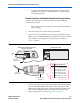
Remote Connection via Network Using Default Factory Settings
Use the following steps to connect remotely to the EthernetBlaster
communications cable:
1 These steps assume no changes have been made to the default
factory settings.
1. Disconnect the power cable from the circuit board.
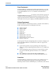
2. Plug one end of a standard CAT 5 UTP 4-pair patch cable into the
Ethernet jack on the EthernetBlaster communications cable, and the
other end into a network port of a switch, router, or hub. See
Figure 1–2 below.
Figure 1–2. Remote Connection via Network
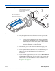
3. Connect the 10-pin female plug of the flexible, PCB-shielded cable
labeled “BLASTER SIDE” to the 10-pin female target port on the
Ethernet communications cable, and the 10-pin female plug of the
cable labeled “TARGET SIDE” to the 10-pin male header on the
target circuit board as shown in Figure 1–3 on page 1–6.
Switch, Router, or Hub
ETHERNET
ETHERNET
DC12V
EthernetBlaster Communications Cable,
Ethernet Port Side View
CAT 5 UTP
Standard Cable
Ethernet Jack
CAT 5 UTP
Standard Cable
Ethernet Connector
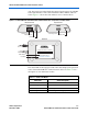
EIA/TIA 568B
1
.
.
.
8
Pin EIA/TIA 568B Wire Color
1
2
3
4
5
6
7
8
White with Orange Stripe
Orange with White Stripe
White with Green Stripe
Blue with White Stripe
White with Blue Stripe
Green with White Stripe
White with Brown Stripe
Brown with White Stripe
Ethernet
Jack