
- Ethernet Blaster Communications Cable User Guide

Altera Corporation 3–3
December 2004 EthernetBlaster Communications Cable User Guide
EthernetBlaster Communications Cable User Guide
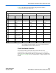
Table 3–2 identifies the 10-pin female plug pin names and the
corresponding programming mode.
1 The circuit board must supply V
CC(TARGET)
and ground to the
EthernetBlaster cable for the I/O drivers.
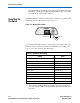
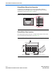
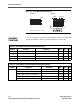
Circuit Board Header Connection
The circuit board's 10-pin male header, which connects to the
EthernetBlaster cable's 10-pin female plug, has two rows of five pins.
These pins are connected to the device’s programming or configuration
pins. Figure 3–3 on page 4 shows the dimensions of a typical 10-pin male
header.
Table 3–2. EthernetBlaster Female Plug Signal Names & Programming Modes
Pin
AS Mode PS Mode JTAG Mode
Signal Name Description Signal Name Description Signal Name Description
1
DCLK
Clock signal
DCLK
Clock signal
TCK
Clock signal
2
GND
Signal ground
GND
Signal ground
GND
Signal ground
3
CONF_DONE
Configuration
done
CONF_DONE
Configuration
done
TDO
Data from
device
4
VCC(TARGET)
Target power
supply
VCC(TARGET)
Target power
supply
VCC(TARGET)
Target power
supply
5
nCONFIG
Configuration
control
nCONFIG
Configuration
control
TMS
JTAG state
machine control
6
nCE
Cyclone chip
enable
–
No connect
–
No connect
7
DATAOUT
Active serial data
out
nSTATUS
Configuration
status
–
No connect
8
nCS
Serial
configuration
device chip select
–
No connect
–
No connect
9
ASDI
Active serial data
in
DATA0
Data to device
TDI
Data to device
10
GND
Signal ground
GND
Signal ground
GND
Signal ground