
- Ethernet Blaster Communications Cable User Guide

Altera Corporation 3–1
December 2004
Chapter 3. EthernetBlaster
Communications Cable
Specifications
Overview
This chapter provides comprehensive information about the
EthernetBlaster communications cable, including the following:
■ EthernetBlaster hardware connections
■ Operating conditions
EthernetBlaster
Hardware
Connections
The EthernetBlaster cable connects to an Ethernet cable with a RJ45 jack
to a 10/100Base-T Ethernet hub/switch (via a straight 8-wire data cable)
or a 10/100Base-T Ethernet port of a PC (via a crossover data cable).
Depending on your connection (remote or direct), data is downloaded
through the EthernetBlaster communications cable to the circuit board
via the connections discussed in this section.
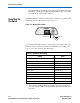
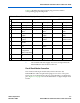
Voltage Requirements
The EthernetBlaster VCC(TARGET) pin must be connected to a specific
voltage for the device being programmed. Connect pull-up resistors to
the same power supply as the EthernetBlaster V
CC(TARGET).
See Table 3–1.
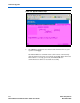
Table 3–1. EthernetBlaster V
CC(TARGET)
Pin Voltage Requirements
Device Family EthernetBlaster VCC Voltage Required
MAX
®
II devices
As specified by V
CCIO
of Bank 1
MAX 7000S devices 5 V
MAX 7000AE and MAX 3000A devices 3.3 V
MAX 7000B devices 2.5 V
Stratix
®
II, Stratix GX, and Stratix devices
As specified by V
CCSEL
Cyclone
™
II, Cyclone, APEX
™
II, APEX 20K, and Mercury
™
devices
As specified by V
CCIO
FLEX 10K
®
, FLEX
®
8000, and FLEX 6000 devices
5 V
FLEX 10KE devices 2.5 V
FLEX 10KA and FLEX 6000A devices 3.3 V
EPC2 devices 5 V or 3.3 V
EPC4, EPC8, and EPC16 devices 3.3 V
EPCS1, EPCS4, EPCS16, and EPCS64 devices 3.3 V