
- Ethernet Blaster Communications Cable User Guide

1–10 Altera Corporation
EthernetBlaster Communications Cable User Guide December 2004
Cable Setup
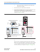
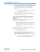
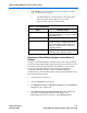
Figure 1–7. Direct Connection to a Computer Using a Standard Cable and a Crossover Adapter
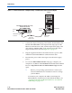
3. Connect the 10-pin female plug of the flexible, PCB-shielded cable
labeled “BLASTER SIDE” to the 10-pin female target port on the
Ethernet communications cable, and the 10-pin female plug of the
cable labeled “TARGET SIDE” to the 10-pin male header on the
target circuit board as shown in Figure 1–3 on page 1–6.
4. Plug the supplied 12.0 VDC wall transformer into a power outlet
and then into the EthernetBlaster communications cable.
5. Reconnect the power cable to the target circuit board to reapply
power.
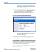
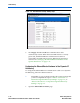
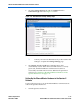
6. To access the EthernetBlaster Status web page, configure your
computer to an address in the 192.168.0.X network domain and then
browse to http://192.168.0.50. The EthernetBlaster login window
opens.
1 Refer to your operating system manual or contact your
network administrator for instruction on how to change
your IP address.
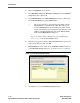
To maintain your computer’s IP address and change the
EthernetBlaster communications cable default IP address, see
“Configuring the EthernetBlaster Hardware to Use Static IP
Addressing” on page 1–11.
Computer
ETHERNET
ETHERNET
ETHERNET
DC12V
EthernetBlaster Communications Cable,
Ethernet Port Side View
EIA/TIA 568B
Connector
CAT 5 UTP
Standard Cable
Ethernet Jac
k
EIA/TIA 568B
Connector
Ethernet
Jack
Crossover
Adapter