
- Ethernet Blaster Communications Cable User Guide

Altera Corporation 1–9
December 2004 EthernetBlaster Communications Cable User Guide
About the EthernetBlaster Communications Cable
1 These steps assume no changes have been made to the
default factory settings.
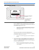
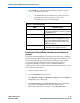
1. Disconnect the power cable from the circuit board.
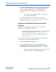
2. Plug the EIA/TIA 568B connector of a crossover CAT 5 UTP 4-pair
patch cable into the Ethernet jack on the EthernetBlaster
communications cable, and the EIA/TIA 568A connector into your
computer. See Figure 1–6 below.
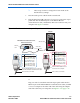
Figure 1–6. Direct Connection to a Computer Using a Crossover Cable
or
Plug one end of a standard CAT5 UTP 4-pair patch cable into the
Ethernet jack on the EthernetBlaster communications cable, and add
a crossover adapter to the other end of the cable. Plug the adapter
end of the cable into your computer. See Figure 1–7 on page 1–10.
Computer
ETHERNET
ETHERNET
DC12V
EthernetBlaster Communications Cable,
Ethernet Port Side View
CAT 5 UTP
Crossover Cable
Ethernet Jack
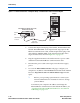
Ethernet EIA/TIA 568A Connector
Connected to the Computer
Pin EIA/TIA 568A Wire Color
1
2
3
4
5
6
7
8
White with Green Stripe
Green with White Stripe
White with Orange Stripe
Blue with White Stripe
White with Blue Stripe
Orange with White Stripe
White with Brown Stripe
Brown with White Stripe
Ethernet
Jack
CAT 5 UTP Crossover Cable
1
. . .
8
Ethernet EIA/TIA 568B Connector Connected
to the EthernetBlaster Communications Cable
Pin EIA/TIA 568B Wire Color
1
2
3
4
5
6
7
8
White with Orange Stripe
Orange with White Stripe
White with Green Stripe
Blue with White Stripe
White with Blue Stripe
Green with White Stripe
White with Brown Stripe
Brown with White Stripe
CAT 5 UTP Crossover Cable
1
. . .
8