
- Ethernet Blaster Communications Cable User Guide


1–6 Altera Corporation
EthernetBlaster Communications Cable User Guide December 2004
Cable Setup
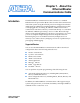
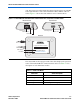
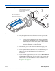
Figure 1–3. Connecting the EthernetBlaster Communications Cable to the Target Circuit Board
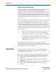
4. Plug the supplied 12.0 VDC wall transformer into a power outlet
and then into the EthernetBlaster communications cable.
1 Always connect the network patch cable as instructed in
step 2 before connecting the power cord. This allows the
EthernetBlaster communications cable to obtain a DHCP
address (if your network is configured to do so). Wait until
the Status LED emits a steady green light.
5. Reconnect the power cable to the circuit board to reapply power.
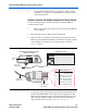
6. If your network supports DHCP, see step 7 on the following page
for configuration instructions. If your network does not support
DHCP, see step 8 on the following page for configuration
instructions.
7. If your network supports DHCP, you can access the EthernetBlaster
Configuration administrative web page using a web browser with
the hostname as the address. The hostname is located on the label
on the base of the EthernetBlaster communications cable as shown
in Figure 1–4 on page 1–7.
10-pin Female Connector (connects
to the target printed circuit board
10-pin male header)
Pin 1 of the Flexible PCB
Shielded-Cable Facing this Side
P
I
N
1
T
A
R
G
E
T
B
L
A
S
T
E
R
S
I
D
E
S
I
D
E
EthernetBlaster
DC12V
ETHERNET