EthernetBlaster Communications Cable User Guide 101 Innovation Drive San Jose, CA 95134 (408) 544-7000 http://www.altera.com UG-120904-1.0 P25-10326-00 Document Version: Document Date: 1.
Copyright © 2004 Altera Corporation. All rights reserved. Altera, The Programmable Solutions Company, the stylized Altera logo, specific device designations, and all other words and logos that are identified as trademarks and/or service marks are, unless noted otherwise, the trademarks and service marks of Altera Corporation in the U.S. and other countries. All other product or service names are the property of their respective holders. Altera products are protected under numerous U.S.
Contents Chapter 1. About the EthernetBlaster Communications Cable Introduction ............................................................................................................................................ 1–1 Supported Devices ........................................................................................................................... 1–1 Power Requirements ........................................................................................................................
Contents iv EthernetBlaster Communications Cable User Guide Altera Corporation
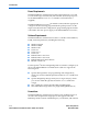
Chapter 1. About the EthernetBlaster Communications Cable Introduction The EthernetBlaster communications cable connects to a standard Ethernet network port with an RJ-45 connector. This cable communicates with client systems using the TCP/IP protocol and supports both static and dynamic IP addressing.
Introduction Power Requirements The EthernetBlaster communications cable requires between 1.5 V and 5.0 V from the target circuit board, and 12.0 VDC (0.875A) input power for the EthernetBlaster VCCSUPPLY (a 12.0 VDC wall transformer is supplied). The EthernetBlaster VCC(TARGET) pin must be connected to the appropriate voltage for the device being programmed.
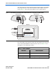
About the EthernetBlaster Communications Cable jack. The target port side includes the 10-pin female target port and LED status light. The base of the cable includes the MAC address and host name. Figure 1–1 shows the side and base views of the hardware. Figure 1–1.
Cable Setup Static & Dynamic IP Addressing The EthernetBlaster communications cable supports both static IP and dynamic IP addressing, the latter by means of Dynamic Host Configuration Protocol (DHCP). By default, the EthernetBlaster cable is configured at the factory to use dynamic IP addressing. Upon power up, the cable attempts to obtain an IP address from your network DHCP server. The Status LED is green and blinking while the network address is being obtained and the cable is initializing.
About the EthernetBlaster Communications Cable 1 For plug and header dimensions, pin names, and operating conditions, see Chapter 3, “EthernetBlaster Communications Cable Specifications.” Remote Connection via Network Using Default Factory Settings Use the following steps to connect remotely to the EthernetBlaster communications cable: 1 These steps assume no changes have been made to the default factory settings. 1. Disconnect the power cable from the circuit board. 2.
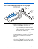
Cable Setup Figure 1–3. Connecting the EthernetBlaster Communications Cable to the Target Circuit Board AS SID TER E as tBl rne e Eth BL ter PIN1 Pin 1 of the Flexible PCB Shielded-Cable Facing this Side TAR G ET SID E 10-pin Female Connector (connects to the target printed circuit board 10-pin male header) ETH ER NE T DC 12V 4. Plug the supplied 12.0 VDC wall transformer into a power outlet and then into the EthernetBlaster communications cable.
About the EthernetBlaster Communications Cable Figure 1–4. MAC Address & Host Name EthernetBlaster Communications Cable Bottom View Ethernet Blaster Copyright 2004 Altera Corporation D0:07:ED:05:XX:XX Host Name: acebXXXX The last 4 digits of the MAC address are the same as the last 4 digits of the host name. Use the hostname as the address to access the EthernetBlaster communications cable configuration administrative web page.
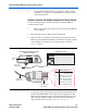
Cable Setup 1 9. To maintain your computer’s IP address and change the EthernetBlaster communications cable default IP address, see “Configuring the EthernetBlaster Hardware to Use Static IP Addressing” on page 1–11. In the EthernetBlaster login window, enter admin as the login and password as the default password. The EthernetBlaster Status page opens, displaying the status of your EthernetBlaster communications cable, including the current IP address. See Figure 1–5. Figure 1–5.
About the EthernetBlaster Communications Cable 1 These steps assume no changes have been made to the default factory settings. 1. Disconnect the power cable from the circuit board. 2. Plug the EIA/TIA 568B connector of a crossover CAT 5 UTP 4-pair patch cable into the Ethernet jack on the EthernetBlaster communications cable, and the EIA/TIA 568A connector into your computer. See Figure 1–6 below. Figure 1–6.
Cable Setup Figure 1–7. Direct Connection to a Computer Using a Standard Cable and a Crossover Adapter Computer ETHERNET EthernetBlaster Communications Cable, Ethernet Port Side View Ethernet Jack ETHERNET ETHERNET Ethernet Jack Crossover Adapter DC12V EIA/TIA 568B Connector CAT 5 UTP Standard Cable EIA/TIA 568B Connector 3.
About the EthernetBlaster Communications Cable 7. In the EthernetBlaster login window, enter admin as the login and password as the default password. The EthernetBlaster Status page opens displaying the status of your EthernetBlaster communications cable including the current IP address. See Figure 1–5. 1 8. See Chapter 2, “Managing Passwords,” to manage your password after initial login.
Cable Setup Figure 1–8. EthernetBlaster Change Settings Page 3. Click Apply. The EthernetBlaster communications cable automatically restarts. When the status LED returns to a steady green state, the EthernetBlaster communications cable has successfully restarted and can now be added to the Quartus II software. See “Setting Up the EthernetBlaster Hardware in the Quartus II Software” on page 1–13.
About the EthernetBlaster Communications Cable 2. Click the Change Settings tab and select DHCP from the Connection Type menu. See Figure 1–8 below. Figure 1–9. EthernetBlaster Change Settings Page 1 3. Contact your network administrator if you do not know the settings to complete the Change Settings page. Click Apply. The EthernetBlaster communications cable automatically restarts.
Cable Setup 2. Choose Programmer (Tools menu). 3. Click Hardware Setup. The Hardware Settings tab of the Hardware Setup dialog box is displayed. 4. Click Add Hardware. The Add Hardware dialog box is displayed. Select EthernetBlaster and click Auto Detect. 1 The server name list is automatically populated with the EthernetBlaster communications cable detected on your subnet if Auto Detect is selected.
About the EthernetBlaster Communications Cable 8. In the Mode list, select the desired mode (Programmer window). Table 1–2 describes each mode. 1 The EthernetBlaster communications cable supports the Joint Test Action Group (JTAG), Passive Serial Programming, and Active Serial modes. Table 1–2. Programming Modes Mode Mode Description Joint Test Action Group (JTAG) Programs or configures all Altera devices supported by the Quartus II software, excluding FLEX 6000 devices.
Cable Setup 1 f See “Setting Up the EthernetBlaster Hardware in the Quartus II Software” on page 1–13 for instructions to add the EthernetBlaster communications cable back into the Quartus II Programmer Hardware setup. For details about programming devices and creating secondary programming files, see the “Programming & Configuration” chapter of the Introduction to Quartus II Manual. For further information, see the Programming module of the Quartus II online tutorial.
Chapter 2.
Managing Passwords 1 When you change the Quartus II remote connection password, client systems using the EthernetBlaster communications cable must remove the hardware from their Quartus II Programmer hardware setup. See Chapter 1, “Removing the EthernetBlaster Hardware from the Quartus II Software Programmer Hardware Setup” for details. The hardware then needs to be added back into the Quartus II software. See Chapter 1, “Setting Up the EthernetBlaster Hardware in the Quartus II Software” for details.
EthernetBlaster Communications Cable Administration The new password takes effect immediately when logging back into the administrative web page. 1 The EthernetBlaster communications cable does not restart when the administrative password is reset. Changing the Quartus II Remote Connection Password To change the Quartus II remote connection password, follow the directions below: 1. 1 2. Open and log into the EthernetBlaster administrative web page in your browser.
Resetting the Hardware The EthernetBlaster communications cable restarts. When the status LED emits a steady green light, the EthernetBlaster has successfully reset and the new password is effective. Resetting the Hardware The EthernetBlaster communications cable reset button is located on the Ethernet port side of the hardware. See Figure 2–3. Figure 2–3.
EthernetBlaster Communications Cable Administration 1 Firmware Upgrade When the EthernetBlaster is reset, existing client systems using passwords other than the factory default must remove the EthernetBlaster hardware from their Quartus II Programmer Hardware Setup. See Chapter 1, “Removing the EthernetBlaster Hardware from the Quartus II Software Programmer Hardware Setup” for instructions on removal of the EthernetBlaster hardware. The hardware then needs to be added back into the Quartus II software.
Firmware Upgrade Figure 2–4. Upgrade Firmware Page 3. Click Browse and then locate and select the firmware file on your system. Click Apply. The EthernetBlaster communications cable restarts automatically after the firmware has been successfully upgraded. When the status LED returns to a steady green state, the EthernetBlaster communications cable has restarted successfully.
Chapter 3. EthernetBlaster Communications Cable Specifications Overview This chapter provides comprehensive information about the EthernetBlaster communications cable, including the following: ■ ■ EthernetBlaster Hardware Connections EthernetBlaster hardware connections Operating conditions The EthernetBlaster cable connects to an Ethernet cable with a RJ45 jack to a 10/100Base-T Ethernet hub/switch (via a straight 8-wire data cable) or a 10/100Base-T Ethernet port of a PC (via a crossover data cable).
EthernetBlaster Hardware Connections EthernetBlaster Ethernet Jack Connection The Ethernet cable Ethernet jack connects to the EthernetBlaster communications cable Ethernet port. The Ethernet jack pin number designations are shown in Figure 3–1 below. Figure 3–1.
EthernetBlaster Communications Cable User Guide Table 3–2 identifies the 10-pin female plug pin names and the corresponding programming mode. Table 3–2.
Operating Conditions Figure 3–3. 10-Pin Male Header Dimensions Top View Side View 0.100 0.025 Sq. 0.100 0.235 Dimensions are shown in inches. Operating Conditions Tables 3–3 through 3–5 summarize the maximum ratings, recommended operating conditions, and DC operating conditions for the cable. Table 3–3. EthernetBlaster Cable Absolute Maximum Ratings Min Max Unit VCC(TARGET) Symbol Target supply voltage Parameter With respect to ground Conditions –0.3 5.
EthernetBlaster Communications Cable User Guide Table 3–5. EthernetBlaster Cable DC Operating Conditions Symbol VIH Parameter Conditions Min Max Unit VCC(TARGET) –0.2 V VCC(TARGET) > 3.3 V 3.1 V High-level input voltage VCC(TARGET) < or = 3.3 V High-level input voltage VIL Low-level input voltage VOH 5.0-V high-level output voltage VCC(TARGET) = 4.5 V, IOH = 20 µA 3.3 V 3.3-V high-level output voltage VCC(TARGET) = 3.0 V, IOH = 20 µA 2.0 V 2.
Revision History ■ ■ Revision History Chapter Date All December 2004 How to Contact Altera Information Type Technical support Refer to the following procedures in Quartus II Help: ● Programming a Single Device or Multiple Devices in JTAG or Passive Serial Mode ● Programming a Single Device in Active Serial Programming Mode ● Selecting the Communications Cable for the SignalTap II Logic Analyzer Refer to the following introduction and overview topics in Quartus® II Help: ● Programmer Introduction ● O